












Archive
10.11.2026


 0
 0
 Touch operator panels Weintek
 Meters-indicators
 Controllers (PID, ON/OFF)
 I/O modules

I/O modules
 Spark protection barrier

Spark protection barrier
 Recorders and archivers

Recorders and archivers
 Meters and converters of electrical network parameters

Meters and converters of electrical network parameters
 Counters, timers, tachometers

Counters, timers, tachometers
 Liquid level indicators and regulators

Liquid level indicators and regulators
 Programmed logical controllers

Programmed logical controllers
 Manual signal transmitters

Manual signal transmitters
 Technological signaling devices

Technological signaling devices
 Power supplies

Power supplies
Codesys PLC controllers
Codesys PLC controllers
 Normalizing converters

Normalizing converters
Galvanic isolation and branching blocks
Galvanic isolation and branching blocks
 Communication interface converters and amplifiers

Communication interface converters and amplifiers
 Analytical instruments

Analytical instruments
 Switching blocks

Switching blocks
Control and protection units
Control and protection units
 GSM communication routers / modems

GSM communication routers / modems
Archive
10.11.2026
Author
A. V. Slobodian
E-mail: arny4work@ukr.net
A stand-alone surge warning system can significantly improve the reliability of gas compressor units without a complete upgrade.
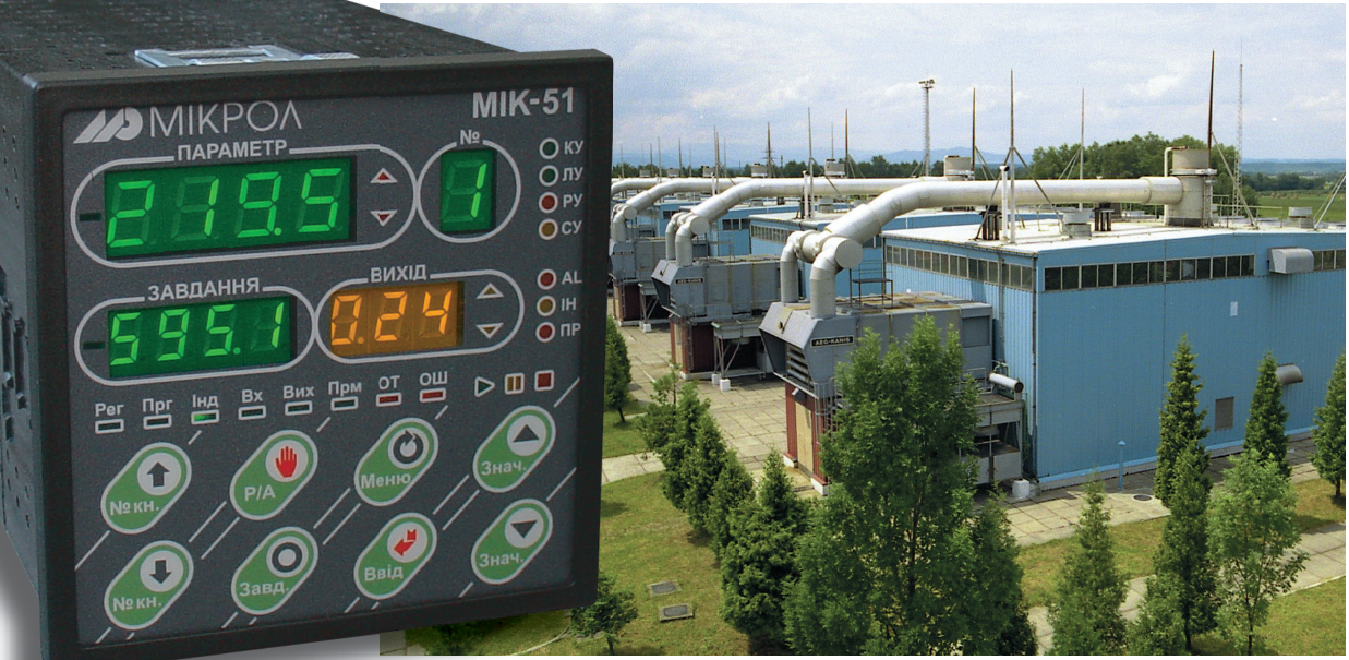
About 70 GTK-10 gas compressor units (GCUs) are currently in operation in Ukraine. Most of them have no surge warning system, so operating personnel learn about surge only at the moment it begins, when there is no longer time to take action to avoid it — only to mitigate its consequences. Surge is a breakdown of gas flow over the compressor impeller blades, possibly with gas breaking back from the discharge nozzle into the suction nozzle, accompanied by severe vibration, noise and abrupt changes in GCU operating parameters.
Each surge event reduces the service life of a GCU by at least 50 operating hours. Developing a surge warning system is therefore an urgent scientific and engineering task, since reliable GCU operation is only possible with an anti-surge system in place. The system described here, which determines the surge margin, is stand-alone and can be installed on a gas compressor unit without a complete upgrade.
Reliable GCU operation affects the operating mode of the pipeline, on which both uninterrupted gas supply to consumers and gas transit through Ukraine depend. However, an analysis of recent research and publications shows that too little research has been done in this area, and there is currently no effective method for determining how far the GCU operating point is from the surge line. Ukraine's gas transmission system now operates a large number of GCUs of various types.
The most common are GCUs with a gas turbine drive, a free power turbine and a centrifugal compressor (C). During pipeline operation, the pressure and temperature at the compressor inlet, gas flow and the number of GCUs running in parallel change noticeably, causing corresponding changes in operating parameters at the compressor station (CS) outlet. The operating mode of the GCU compressor changes constantly during operation due to changes in gas consumption, gas composition and ambient conditions, as well as changes in the technical condition of the GCU as a whole. The main GCU operating parameters are the gas pressure at the compressor inlet (Pin) and outlet (Pout), rotor speed, gas temperature at the compressor inlet and outlet, and the temperature of combustion products upstream of the high-pressure turbine (HPT).
Automatic control of GCU operating parameters is well researched. For example, automation systems commissioned back in the 1970s still operate successfully. What matters, however, is controlling the GCU in modes close to surge and during surge itself, especially for GCUs not equipped with modern anti-surge systems.
Analysis shows that most modern GCU automatic control systems (ACS) determine the operating point and surge margin by calculating the gas flow through the compressor suction confuser and comparing it with the compressor's static characteristics in "pressure ratio — flow volume" coordinates. This is the so-called indirect method. Its advantage is the ability to see the current gas flow through the compressor and to track trends in the pipeline and GCU operating mode long before surge occurs.
The drawbacks of the indirect method include a large error (up to 10 % at best) in determining the surge line. This is due to the inaccuracy of measuring gas flow via the differential pressure across the converging confuser (dPk). Over time, the compressor characteristics change, and results obtained by the indirect method acquire additional error. This affects the surge margin calculation and, in turn, decisions made by operating personnel and the operation of an active anti-surge system, if there is one.
The second well-known method is the direct method, which measures pulsations of dPk. By analyzing gas flow oscillations in the compressor, the actual surge line can be determined and the compressor's operating range extended up to the edge of the pre-surge zone. The advantages of this method are its accessibility (no specific compressor characteristics need to be known) and its independence from the accuracy of dPk measurement (what matters is how the parameter changes). The drawback is that, when using only the direct method, compressor station personnel cannot see the GCU approaching the surge zone while it is operating far from it.
Thus, the unresolved part of the problem today is creating a surge warning system (SWS) that determines the GCU operating point and combines the advantages of each surge margin calculation method.
The aim of this article is to describe an SWS that determines the GCU operating point and surge margin with accuracy and speed sufficient for reliable GCU operation. This will save GCU service life, help avoid unplanned equipment repairs and allow fuel gas to be used efficiently.
Installing an SWS is an expensive solution, since anti-surge systems are mostly part of the GCU ACS and are installed when the automation is replaced. This process is long and costly. Given the above, an inexpensive surge warning system has considerable practical value.
A stand-alone SWS is the only way to protect the service life of GCUs that lack a modern ACS from the consequences of surge. This is supported by OPC (OLE for Process Control) technology, which allows a large number of clients to access real-time data simultaneously. Naturally, such data access opens up wide opportunities for scientific analysis using various software packages, by operations specialists and by researchers. Accumulating and analyzing data from different types of GCUs is a prerequisite for creating adaptive and intelligent SWSs.
The system consists of primary measuring transducers, a programmable logic controller, an interface converter and a workstation running a SCADA system and other software.
Table 1 lists the GCU process parameters required by the system, together with the specifications of the measurement channels and the primary transducers.
| Parameter | Channel | Transducer | Engineering units | Signal |
|---|---|---|---|---|
| Gas differential pressure across the converging confuser | dPk | Honeywell 3000 series | 0–0.15 MPa | 4–20 mA |
| Gas pressure at compressor inlet | Pin | TEX UAG97L | 0–10 MPa | 4–20 mA |
| Gas pressure at compressor outlet | Pout | TEX UAG97L | 0–10 MPa | 4–20 mA |
| High-pressure turbine speed | nHPT | VTsT-1/L | 0–5000 rpm | Interface* |
| Low-pressure turbine speed | nLPT | VTsT-1/L | 0–5000 rpm | Interface* |
* — Modbus or OPC interface
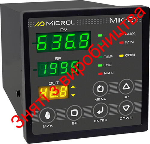
All of these parameters except dPk are already used by the GCU centralized monitoring and control system (CMCS) (Fig. 1), so no additional sensors need to be installed. These signals are wired into the MIK-51 programmable microprocessor controller.
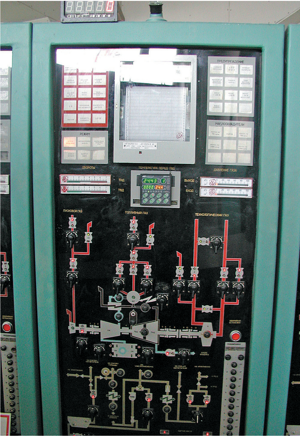
Fig. 1. GTK-10 CMCS operator panel with a built-in MIK-51 controller
To determine the capacity of the NZL 520-12-1 compressor, the differential pressure is measured across the suction chambers between the compressor inlet nozzle and the impeller inlet. Machining the confuser surface to a 0.1 mm tolerance ensures that confusers are manufactured identically and that the flow coefficients of the suction chambers are equal for all compressors of the same type. Pressure taps upstream of the suction chamber must be located on the inlet pipeline before the compressor nozzle. The volumetric capacity of the compressor at suction conditions is determined by formula (1):
Qs = A · l · √(dPk / γ) [m3/min], (1)
where dPk is the differential pressure across the suction chamber, mm Hg;
γ is the specific weight of gas upstream of the compressor, kg/m3;
A is the flow coefficient, calculated from the chamber calibration results using a flow diagram on a test bench (compressors of the same type have the same value of A). For example, for the 520-12-1 compressor, A = 128.8;
l is the correction for gas compression in the chamber, calculated from the chamber calibration results.
The relative gas density upstream of the compressor is determined by formula (2):
γn = 1033 / (293 · R) = 35.2 / R [kg/m3], (2)
where R is the gas constant.
The formula for l is given for a gas adiabatic index of k = 1.31:
l = 1 − 1.385 · 10−3 · Δp / pin. (3)
Knowing the compressor's volumetric capacity, it can be compared with the rated volumetric capacity of the compressor for the given GCU operating mode. To do this, the gas compressibility factor is determined and a nomogram is used to calculate how close the GCU is to the surge point. To automate the calculations, the nomogram curves (9 in total) were approximated by third-order polynomials, whose coefficients are stored in the controller program, and the relevant curve is interpolated in real time.
The surge-free operation condition is met when:
Qs / Qs min > 1.1, (4)
where Qs min is the minimum capacity for the given relative reduced speed of the LPT rotor (according to the compressor characteristic).
The upper level of the system was developed using a demo version of the Simatic WinCC SCADA package. The system has no highly complex controls, so anyone with basic SCADA knowledge can easily implement it in the same environment used for the compressor station or compressor shop ACS — thereby saving considerable money on a SCADA package. If the site has no SCADA package at all, or there are objective reasons why it cannot be upgraded, an inexpensive SCADA system can be purchased from the manufacturer of the MIK-51 controller. The equipment cost per GCU makes the system affordable for every compressor station.
This surge warning and operating point system for GTK(GTNR)-10 units, based on analyzing changes in the process parameters dPk, Pin, Pout and nLPT, has been developed and put into trial operation at compressor shop No. 2 of the Dolyna Line Production Department of Main Gas Pipelines (Prykarpattransgaz). At this stage, calculations are performed using the indirect method. Data is collected by the MIK-51 microprocessor controller. The dynamics of all input parameters are analyzed, which makes it possible to work towards implementing a dynamic method for determining the surge margin.
The system makes it possible to determine the GCU operating point and surge margin using the differential pressure across the converging confuser. Unlike static methods, the implemented elements of GCU parameter dynamics analysis are not strictly tied to measurement accuracy.
The novelty of the system lies in the ability to use different surge margin methods simultaneously, combining the advantages of the systems described and compensating for their drawbacks. The system does not require large-scale work or replacement of the existing automation — it complements it. Using a programmable logic controller in the surge warning system makes it possible to change the controller logic quickly, which is essential when conducting research, developing new methods and improving existing ones.
The system also provides a platform with wide opportunities for further research. Plans include studying the use of artificial neural networks and fuzzy logic in surge control, in determining the dynamics of GCU operating parameters and in automatic analysis of the operating mode. Broad real-time communication capabilities over industrial, local and global networks make it possible to process and analyze the data as efficiently as possible in different environments.
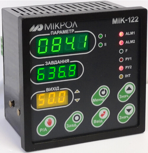
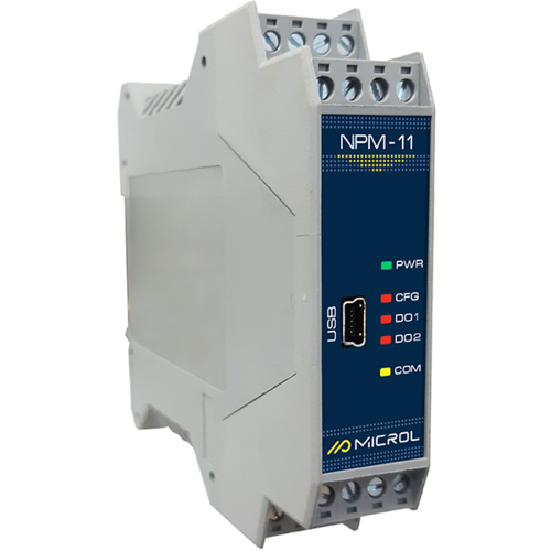
The MIK-51 controller from the Ukrainian manufacturer Microl (Ivano-Frankivsk), on which the system described in this article is based, is a compact, low-channel-count, multifunctional industrial microprocessor controller designed for automatic control and logic control of industrial processes. Its architecture allows control loops to be switched on, off, over and reconfigured manually or automatically, and all these operations are bumpless regardless of the complexity of the control structure. In addition to processing analog signals, the MIK controller performs logic operations on signals and generates analog, pulse and digital control signals. Logic function blocks form a sequential control program that checks the conditions for each step, sets a monitoring time for each step and performs conditional or unconditional jumps to a specified step.
The MIK-51 has operator controls on its front panel. They make it possible to change operating modes manually, enter setpoints, control program execution, operate actuators manually, monitor signals and display errors. MIK controllers can also be combined into a local bus-type control network with an RS-485 interface and the Modbus protocol — up to 32 controllers.
The MIK-51 processes data and transmits it via Modbus RTU to the BPI-52 interface converter, from which the data goes over USB 2.0 to a workstation (PC) with an OPC server. This makes it possible to analyze the data using different methods and compare the results without spending extra time on synchronizing, processing and transferring data.
The controller is programmed from the front-panel keys, from a PC, or with dedicated software — the ALFA visual FBD program editor. The programming language implemented in the system is Function Block Diagram. The library contains more than 50 types of ROM-resident function blocks for continuous and discrete data processing, including PID control blocks and blocks for mathematical, dynamic, nonlinear, analog-to-discrete and logic operations. The total time spent on servicing the function blocks and the interface channel is less than the 0.1 s cycle time. The programming system complies with IEC 1131-3 and is designed for developing data acquisition and process control application software that runs on programmable controllers.
For more information about the products mentioned in this article, please contact Microl LLC:
+38 (0342) 502-701
+38 (067) 359-70-90
+38 (095) 092-07-28
sale@microl.ua, microl_zbut@microl.ua, zbutmicrol@gmail.com
www.microl.ua
Technical support:
+38 (0342) 502-702
+38 (067) 704-00-29
+38 (095) 302-37-57
support@microl.ua, supmicrol@gmail.com
Originally published in Mir Avtomatizatsii (World of Automation) magazine, February 2008.
Open the booklet / download PDF