0
0
 0
0
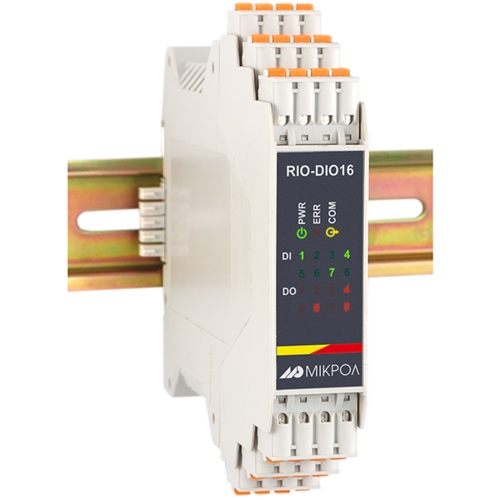
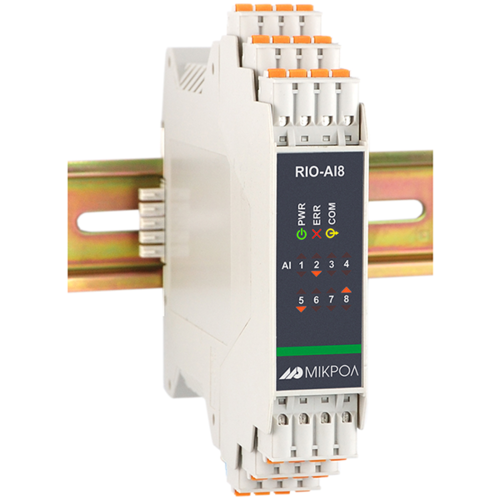
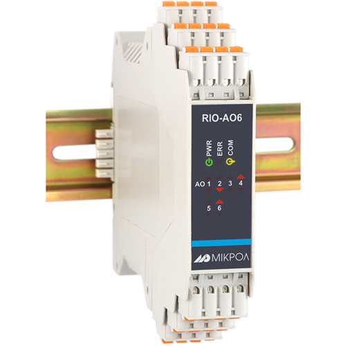
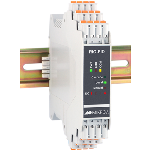
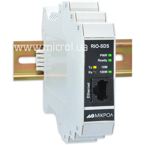
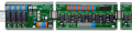
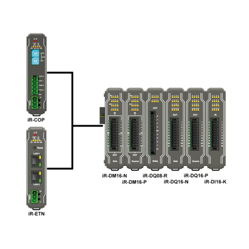
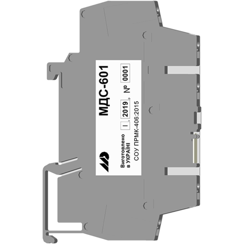
I/O modules
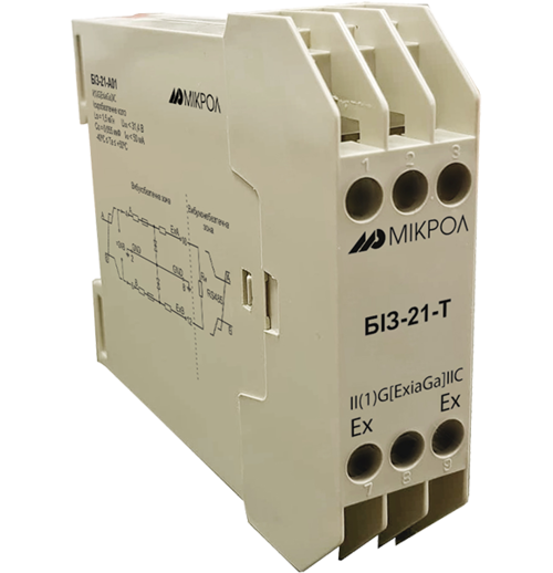
Spark protection barrier
Recorders and archivers
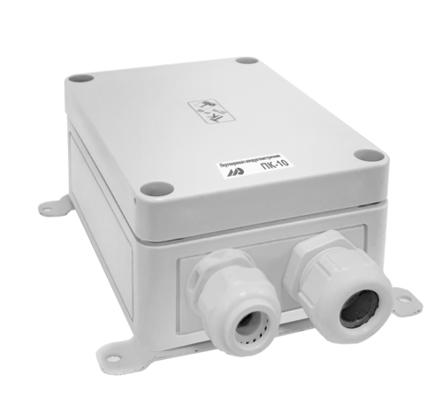
Meters and converters of electrical network parameters
Counters, timers, tachometers
Liquid level indicators and regulators
Programmed logical controllers
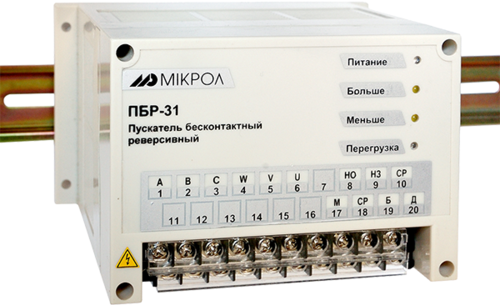
Manual signal transmitters
Technological signaling devices
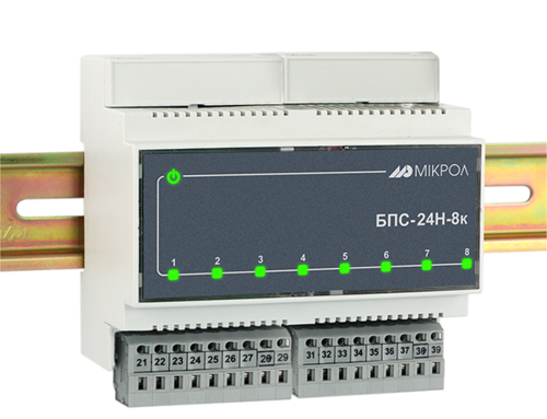
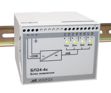
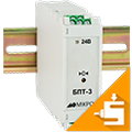
Power supplies
Codesys PLC controllers
Normalizing converters
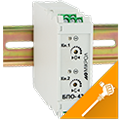
Galvanic isolation and branching blocks
Communication interface converters and amplifiers
Analytical instruments
Switching blocks
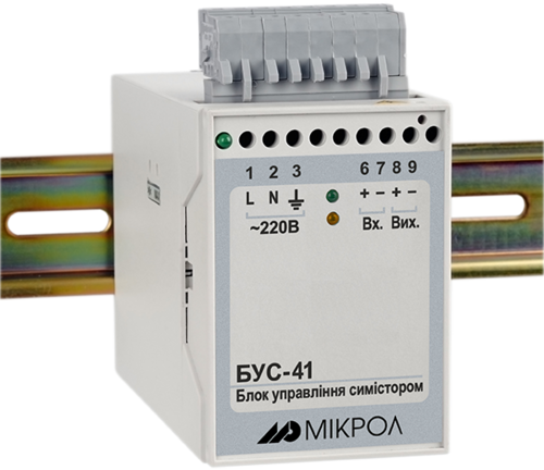
Control and protection units
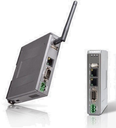
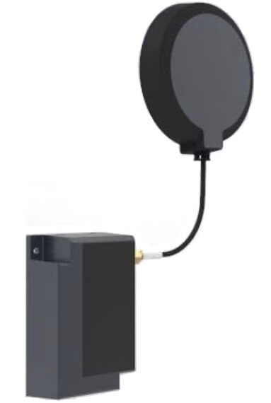
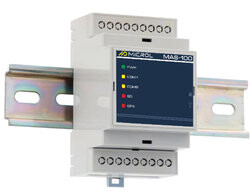
GSM communication routers / modems
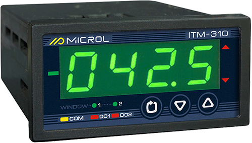
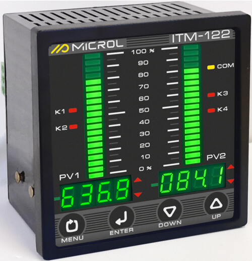
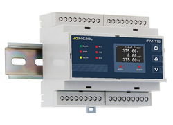
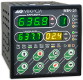
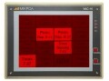
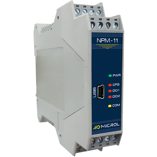
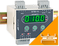
Indicator of three-phase network parameters

IPM-103-1

IPM-103-2

IPM-103-3
Type of power supply:
Three-phase
Three-phase
Three-phase
Input signal type:
AC voltage
AC current
AC voltage
AC current
AC voltage
AC current
Quantity inputs:
2, separately I and U
2, separately I and U
2, separately I and U
Direct connection:
~ (1...400 V), frequency from 45 to 65 Hz
~ (1...400 V), frequency from 45 to 65 Hz
~ (1...400 V), frequency from 45 to 65 Hz
Through an external transformer:
~ (1×10^-3...4000×10^3 V), frequency from 45 to 65 Hz
~ (1×10^-3...4000×10^3 V), frequency from 45 to 65 Hz
~ (1×10^-3...4000×10^3 V), frequency from 45 to 65 Hz
Measurement update period:
1.0 seconds
1.0 seconds
1.0 seconds
Resolution:
0.1 (on the indicator) V
0.1 (on the indicator) V
0.1 (on the indicator) V
Limit of the main combined measurement error:
± 0,25 %
± 0,25 %
± 0,25 %
Maximum permissible input voltage value (no more than 1 s):
800,0 V
800,0 V
800,0 V
Direct connection:
from 0.05 to 5.0 А
from 0.05 to 5.0 А
from 0.05 to 5.0 А
Through an external transformer:
from (0.05x10^-3 ... 50.0x10^3) А
from (0.05x10^-3 ... 50.0x10^3) А
from (0.05x10^-3 ... 50.0x10^3) А
Measurement update period:
1.0 seconds
1.0 seconds
1.0 seconds
Resolution:
0.01 (on the indicator)
0.001 (via the interface)
0.01 (on the indicator)
0.001 (via the interface)
0.01 (on the indicator)
0.001 (via the interface)
Limit of the main combined measurement error:
± 0,25 %
± 0,25 %
± 0,25 %
Maximum permissible input current (for no more than 1 s):
10.0 А
10.0 А
10.0 А
Power components measured:
active, W/kW (instantaneous, average, accumulated, total and phase-by-phase)
eactive, VAR/kVAR (instantaneous, average, accumulated, total and phase-by-phase)
full, VA/kVA (instantaneous, average, accumulated, total and phase-by-phase)
active, W/kW (instantaneous, average, accumulated, total and phase-by-phase)
eactive, VAR/kVAR (instantaneous, average, accumulated, total and phase-by-phase)
full, VA/kVA (instantaneous, average, accumulated, total and phase-by-phase)
active, W/kW (instantaneous, average, accumulated, total and phase-by-phase)
eactive, VAR/kVAR (instantaneous, average, accumulated, total and phase-by-phase)
full, VA/kVA (instantaneous, average, accumulated, total and phase-by-phase)
Computation time:
1.0 seconds
1.0 seconds
1.0 seconds
Limit of the basic combined measurement error:
± 0.5 %
± 0.5 %
± 0.5 %
Measuring range (in the operating power range):
from 0.0 to 1.0
from 0.0 to 1.0
from 0.0 to 1.0
Measurement update period:
1.0 seconds
1.0 seconds
1.0 seconds
Limit of the main combined measurement error:
± 1.0 %
± 1.0 %
± 1.0 %
First harmonic frequency measurement range:
from 45.0 Hz to 65.0 Hz
from 45.0 Hz to 65.0 Hz
from 45.0 Hz to 65.0 Hz
Measurement update period:
1.0 seconds
1.0 seconds
1.0 seconds
Limit of the basic combined measurement error:
± 0,15 %
± 0,15 %
± 0,15 %
Galvanic isolation:
• Input circuits are isolated from other circuits.
• Galvanic isolation voltage is not less than 2500 V.
• Input circuits are isolated from other circuits.
• Galvanic isolation voltage is not less than 2500 V.
• Input circuits are isolated from other circuits.
• Galvanic isolation voltage is not less than 2500 V.
Quantity of discrete outputs:
3
2
-
Types of discrete outputs:
• NPN transistor: up to 40V, 100mA
• Closing relay: up to 230V, 5A
• NPN transistor: up to 40V, 100mA
• Closing relay: up to 230V, 5A
-
Data exchange interface:
RS-485
USB
RS-485
USB
RS-485
USB
Data exchange protocol:
Modbus RTU
Modbus RTU
Modbus RTU
Digital display:
OLED display
OLED display
OLED display
Supply voltage:
Alternating current: 230 V
Alternating current: 230 V
Alternating current: 230 V
Power consumption:
Alternating current: ≤ 2.0 VА
Alternating current: ≤ 2.0 VА
Alternating current: ≤ 2.0 VА
Non-volatile memory:
Yes, EEPROM
Yes, EEPROM
Yes, EEPROM
Galvanic isolation:
• Full. All nodes are isolated from each other
• Galvanic (electrical) isolation voltage not less than 500 V. Inputs not less than 2500 V.
• Full. All nodes are isolated from each other
• Galvanic (electrical) isolation voltage not less than 500 V. Inputs not less than 2500 V.
• Full. All nodes are isolated from each other
• Galvanic (electrical) isolation voltage not less than 500 V. Inputs not less than 2500 V.
Installation type:
for DIN rail mounting
for DIN rail mounting
for DIN rail mounting
Weight, not more than:
not more than 0.3 kg
not more than 0.3 kg
not more than 0.3 kg
Case size (HxWxD):
98х100х57 mm
98х100х57 mm
98х72х57 mm
Degree of protection:
IP20
IP20
IP20
Ambient temperature:
-40 °C to +70 °C
-40 °C to +70 °C
-40 °C to +70 °C
Number of outputs:
1
3
-
Output type:
active output
active output
-
Ranges of possible output signals:
0 to 5 mA / R ≤ 2000 Ω
0 to 20 mA / R ≤ 500 Ω
4 to 20 mA / R ≤ 500 Ω
0 to 10 V / R ≤ 2 кΩ
0 to 5 mA / R ≤ 2000 Ω
0 to 20 mA / R ≤ 500 Ω
4 to 20 mA / R ≤ 500 Ω
0 to 10 V / R ≤ 2 кΩ
-