0
0
 0
0
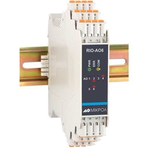
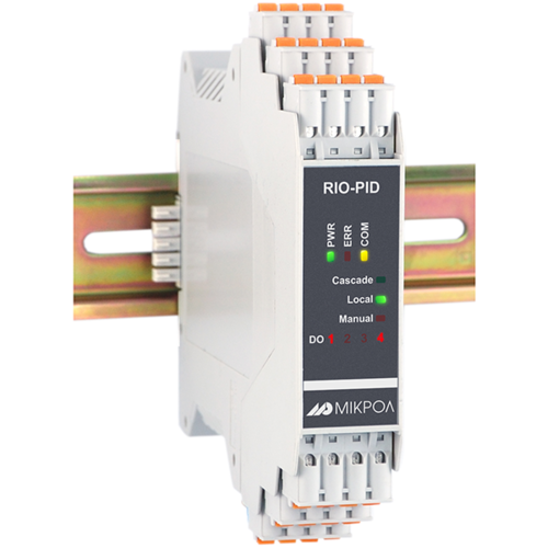
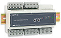
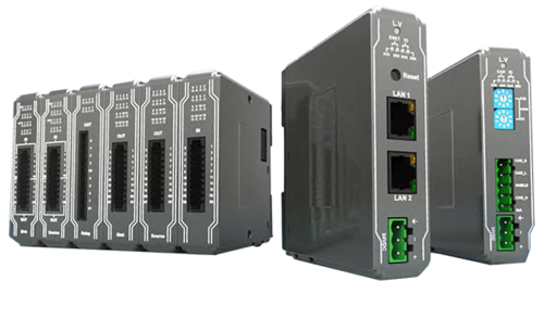
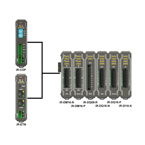
I/O modules
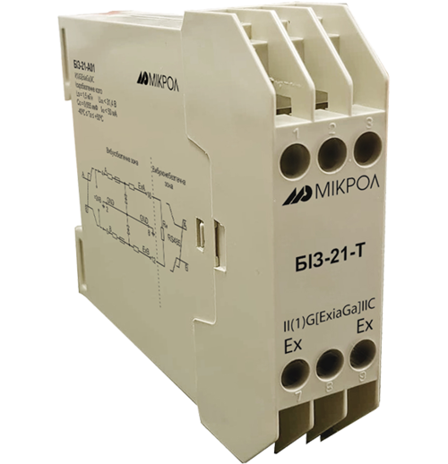
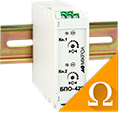
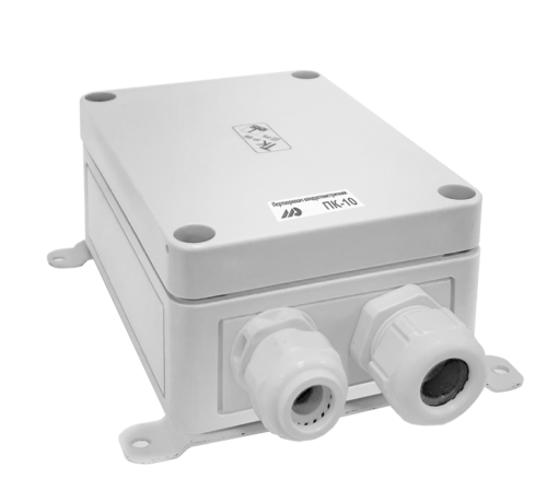
Spark protection barrier
Recorders and archivers
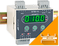
Meters and converters of electrical network parameters
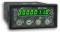
Counters, timers, tachometers
Liquid level indicators and regulators
Programmed logical controllers
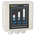
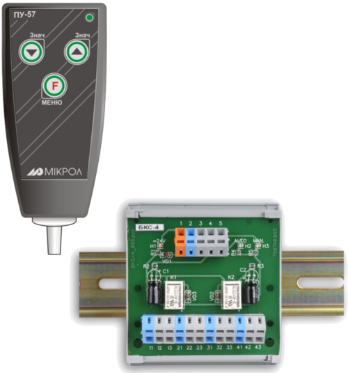
Manual signal transmitters
Technological signaling devices
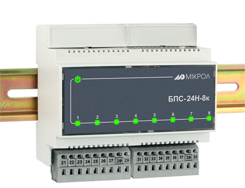
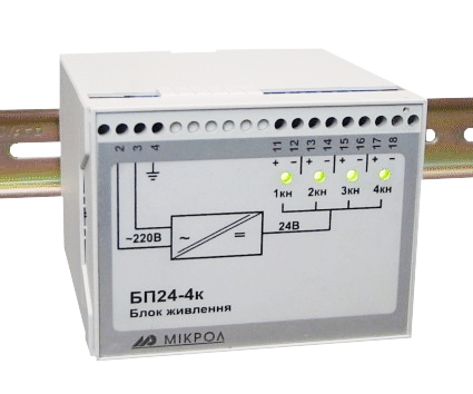
Power supplies
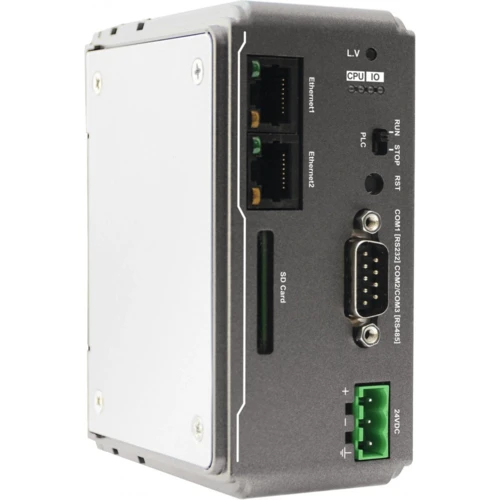
Codesys PLC controllers
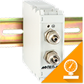
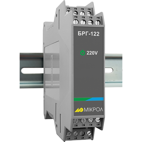
Normalizing converters
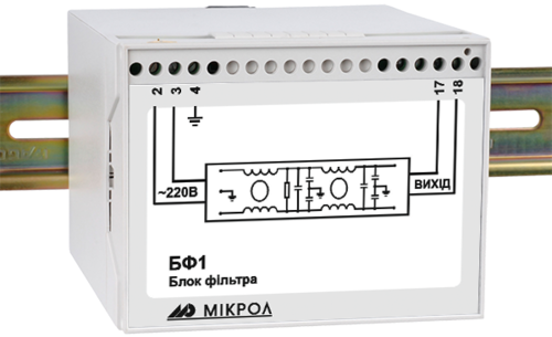
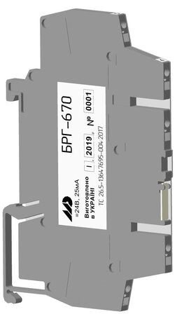
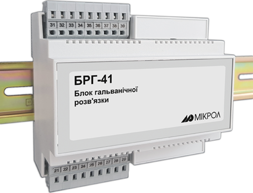
Galvanic isolation and branching blocks
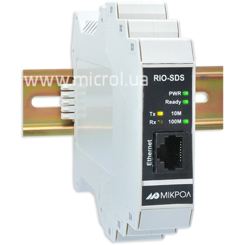
Communication interface converters and amplifiers
Analytical instruments
Switching blocks
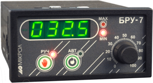
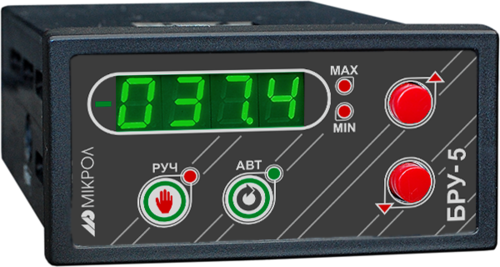
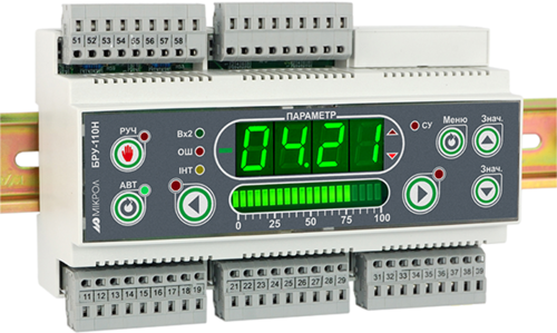
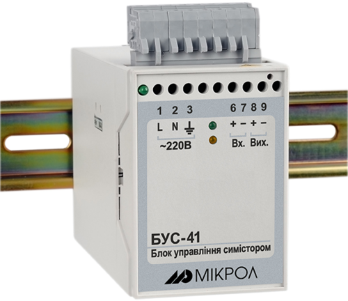
Control and protection units
GSM communication routers / modems
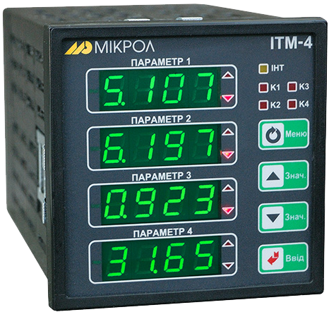
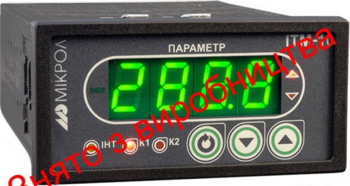
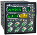
Four-Channel Technological Parameter Indicator with Archiving

ІТМ-304

ІТМ-4

МТР-138

ІТМ-16

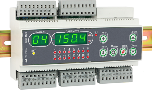
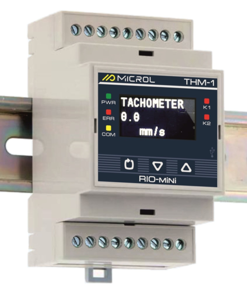
ІТМ-16Н
Device type:
Technological indicator
Technological indicator
Technological indicator
Technological indicator
Technological indicator
Additional features:
Input signal conversion
Alarms
Integration
Mathematical functions
Archiving
Input signal conversion
Alarms
Mathematical functions
Input signal conversion
Alarms
Mathematical functions
Regulation
Input signal conversion
Alarms
Input signal conversion
Alarms
Quantity of analog inputs:
4
4
8
group entry
16
group entry
16
group entry
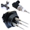
Types of input sensors and signals:
0-5 mA, 0-20 mA, 4-20 mA, -5-5 mA, -20-20 mA
0-10 V, 0-100 mV, -10-10 V, -100-100 mV
Cu 50, Cu 100, Pt 50P, Pt 100P, Pt50, Pt100, Pt500, Pt1000
Type: K,L,N,J,S,R,B,T,E,A-1, A-2, A-3
0-150 Ohm, 0-300 Ohm, 0-1200 Ohm, 0-2500 Ohm
0-5 mA, 0-20 mA, 4-20 mA
0-75 mВ , 0-200 mВ , 0-2 V, 0-10 V
Cu 50, Cu 100, Pt 50P, Pt 100P, Pt50, Pt100, Pt500, Pt1000
Type: K,L,J,S,B,E,A-1
0-1 kΩ
0-5 mA, 0-20 mA, 4-20 mA
0-75mВ, 0-1 V, 0-10 V
Cu 50, Cu 100, Pt 50P, Pt 100P, Pt50, Pt100, Pt1000
Type: K,L,J,S,B,E,A-1
NTC 10 kOhm
0-5 mA, 0-20 mA, 4-20 mA
0-75 mV, 0-200mV, 0-1 V, 0-10 V
Cu 50, Cu 100, Pt 50P, Pt 100P, Pt50, Pt100, Pt1000
Type: K,L,J,S,B,E,A-1
0-5 mA, 0-20 mA, 4-20 mA
0-75 mV, 0-200mV, 0-1 V, 0-10 V
Cu 50, Cu 100, Pt 50P, Pt 100P, Pt50, Pt100, Pt1000
Type: K,L,J,S,B,E,A-1
Limit of the basic combined measurement error:
≤ 0.2 %
≤ 0.4 % (when switching to another sensor type, without calibration)
≤ 0.2 %
≤ 0.2 %
≤ 0.2 %
≤ 0.2 %
Рolling cycle time:
up to 0.1 seconds
up to 0.1 seconds
up to 0.1 seconds
up to 0.1 seconds
up to 0.1 seconds
Galvanic isolation:
• Input isolated from other circuits.
• Galvanic isolation voltage is not less than 500 V.
• Input isolated from other circuits.
• Galvanic isolation voltage is not less than 500 V.
• Group. Inputs are isolated from other circuits.
• Galvanic isolation voltage is not less than 500 V.
• Group. Inputs are isolated from other circuits.
• Galvanic isolation voltage is not less than 500 V.
• Group. Inputs are isolated from other circuits.
• Galvanic isolation voltage is not less than 500 V.
Switching to another sensor type:
User-selectable sensor type switching. No calibration required.
User-configurable, calibration required
User-configurable, calibration required
Group input, one type for all inputs
User-configurable, calibration required
Group input, one type for all inputs
User-configurable, calibration required
Group input, one type for all inputs
Quantity of discrete inputs:
Not included
Not included
Not included
In the basic: Not included
Depending on the expansion module model: maximum 32
In the basic: Not included
Depending on the expansion module model: maximum 32
Number of outputs:
1 (option)
1
up to 4 (option)
1 (expansion module only)
1 (expansion module only)
Output type:
active
active
active
active
active
Ranges of possible output signals:
0 to 5 mA / R ≤ 2000 Ω
0 to 20 mA / R ≤ 500 Ω
4 to 20 mA / R ≤ 500 Ω
0 to 10 V / R ≤ 2 кΩ
0 to 5 mA / R ≤ 2000 Ω
0 to 20 mA / R ≤ 500 Ω
4 to 20 mA / R ≤ 500 Ω
0 to 10 V / R ≤ 2 кΩ
0 to 5 mA / R ≤ 2000 Ω
0 to 20 mA / R ≤ 500 Ω
4 to 20 mA / R ≤ 500 Ω
0 to 10 V / R ≤ 2 кΩ
0 to 5 mA / R ≤ 2000 Ω
0 to 20 mA / R ≤ 500 Ω
4 to 20 mA / R ≤ 500 Ω
0 to 10 V / R ≤ 2 кΩ
0 to 5 mA / R ≤ 2000 Ω
0 to 20 mA / R ≤ 500 Ω
4 to 20 mA / R ≤ 500 Ω
0 to 10 V / R ≤ 2 кΩ
The limit of the main combined error of the output signal formation:
≤ 0.2 %
≤ 0.2 %
≤ 0.2 %
≤ 0.2 %
≤ 0.2 %
Quantity of discrete outputs:
8 (optional)
4
8
In the basic: 2 (NPN transistor)
Depending on the expansion module model: maximum 32
In the basic: 2
Depending on the expansion module model: maximum 32
Types of discrete outputs:
• NPN transistor: up to 40V, 100mA
• Closing relays: up to 230V, 5A
• NPN transistor: up to 40V, 100mA
• Switching relay: up to 230V, 8A
• Opto-triac: up to 300 V, 0.7 A
• NPN transistor: up to 40V, 100mA
• Closing relay: up to 230V, 5A
• NPN transistor: up to 40V, 100mA
• Closing relay: up to 230V, 5A
• NPN transistor: up to 40V, 100mA
• Closing relay: up to 230V, 5A
Data exchange interface:
RS-485
USB
Ethernet
RS-485
RS-485
RS-485
RS-485
Data exchange protocol:
Modbus RTU
Modbus TCP
Modbus RTU
Slave
Modbus RTU
Slave
Modbus RTU
Slave
Modbus RTU
Slave
Indication type:
Seven-segment, digital
4-digit display
Seven-segment, digital
Seven-segment, digital
Seven-segment, digital
Seven-segment, digital
Indication accuracy:
Four categories
Four categories
Four categories
Four categories
Four categories
Supply voltage:
Alternating current: 230 V
Direct current: 24 V
Alternating current: 230 V
Direct current: 24 V
Alternating current: 230 V
Direct current: 24 V
Alternating current: 230 V
Direct current: 24 V
Alternating current: 230 V
Direct current: 24 V
Power consumption:
Direct current: no more than 400 mA
Alternating current: no more than 7 VA
Alternating current: ≤ 7.3 VА
Direct current: no more than 310 mA
Alternating current: ≤ 5.8 VА
Direct current: no more than 250 mA
Alternating current: ≤ 10 VА
Direct current: no more than 350 mA
Alternating current: ≤ 5 VА
Direct current: no more than 300 mA
Availability of a built-in power supply for inputs:
Yes, optional, if specified in the order
= 24 V, 25 mA (two channels)
ption, provided that a 4..20mA signal is ordered
= 24 V, 25 mА
Not included
Yes, optional, if specified in the order
= 24 V, 25 mA (two channels)
Not included
Non-volatile memory:
Yes, EEPROM
Yes, EEPROM
Yes, EEPROM
Yes, EEPROM
Yes, EEPROM
Galvanic isolation:
• Full. All components of the device are isolated from each other.
• Galvanic (electrical) isolation voltage (for outputs and interface), not less than 500 V
• Full. All components of the device are isolated from each other.
• Galvanic (electrical) isolation voltage (for outputs and interface), not less than 1500 V
• Full. All components of the device are isolated from each other.
• Galvanic (electrical) isolation voltage (for outputs and interface), not less than 500 V
• Full. All components of the device are isolated from each other.
• Galvanic (electrical) isolation voltage (for outputs and interface), not less than 500 V
• Full. All components of the device are isolated from each other.
• Galvanic (electrical) isolation voltage (for outputs and interface), not less than 500 V
Installation type:
Shield
Shield
Shield
Shield
DIN-rail
Case size (HxWxD):
96х96х153 mm
96х96х135 mm
96х96х135 mm
96х96х135 mm
110х160х58 mm
Weight, not more than:
не більше 0,25 kg
не більше 0,5 kg
не більше 1,0 kg
не більше 1,0 kg
не більше 0,5 kg
Degree of protection:
IP30
IP30
IP30
IP30
IP30
Ambient temperature:
-40 °C to +70 °C
-40 °C to +70 °C
-40 °C to +70 °C
-40 °C to +70 °C
-40 °C to +70 °C