









Archive
09.11.2026


 0
 0
 Touch operator panels Weintek
 Meters-indicators
 Controllers (PID, ON/OFF)
 I/O modules

I/O modules
 Spark protection barrier

Spark protection barrier
 Recorders and archivers

Recorders and archivers
 Meters and converters of electrical network parameters

Meters and converters of electrical network parameters
 Counters, timers, tachometers

Counters, timers, tachometers
 Liquid level indicators and regulators

Liquid level indicators and regulators
 Programmed logical controllers

Programmed logical controllers
 Manual signal transmitters

Manual signal transmitters
 Technological signaling devices

Technological signaling devices
 Power supplies

Power supplies
Codesys PLC controllers
Codesys PLC controllers
 Normalizing converters

Normalizing converters
Galvanic isolation and branching blocks
Galvanic isolation and branching blocks
 Communication interface converters and amplifiers

Communication interface converters and amplifiers
 Analytical instruments

Analytical instruments
 Switching blocks

Switching blocks
Control and protection units
Control and protection units
 GSM communication routers / modems

GSM communication routers / modems
Archive
09.11.2026
Author
Yurii Tverskoi, PhD, Senior Researcher, Armakipservis LLC (Kyiv), National Technical University of Ukraine "KPI"
This article discusses how to build an automatic furnace draft control system for a boiler using modern microprocessor-based automation equipment with a variable frequency drive (inverter) in the control loop. A method for a step-by-step transition from the existing system to the proposed one is described. The system can significantly reduce the power consumed by the induced-draft fan drive of a boiler unit that spends most of its time in modulating mode. The solution is intended for small and medium-capacity boiler units.
Government calls to use energy resources carefully and to introduce energy-saving technologies seem strange, to say the least, for a country that has embarked on a market economy. A market economy based on fierce competition implies such an approach "by default". Yet our Slavic brethren, firmly sticking to the principle "until the thunder strikes…", wait for their moment. At last it has come ("every cloud has a silver lining…"). Calls for urgent action immediately appeared, summer seminars in Yalta are already being organized, and so on. However, some solutions are right on the surface. As an inventor I have known for a long time used to say: "When I walk around the plant (the shop…), I feel as if I am walking on banknotes." Quick results in heat power engineering can be achieved by paying proper attention to the furnace draft control loop of the boiler unit.
Technical literature written 30 years ago already suggested speed control as one possible way to regulate furnace draft — either by changing the fan speed with hydraulic couplings or by changing the speed of the electric drive. This method was shown to be the most economical.
The arrival of variable frequency drives (inverters) on the market has made it possible to put this long-standing technical idea into practice.
1.1. Characteristics of the controlled process
In terms of draft, the controlled object consists of the furnace (combustion chamber) and the flue ducts up to the induced-draft fan suction inlets, arranged in series. A slight draft of 2–3 mm H₂O (20–30 Pa) in the upper part of the furnace is needed for stable flame in the combustion zone and to prevent combustion products from blowing out of the boiler; it also indirectly reflects the material balance between the combustion air (the fuel oxidizer) and the flue gases (the combustion products). The input control action is the flow of extracted flue gases, determined by the induced-draft fan capacity. The external disturbance is a change in the airflow supplied to the furnace when the boiler's heat load changes. Internal disturbances are upsets of the gas–air mode.
The dynamic properties of the controlled object are characterized by the absence of dead time, low inertia (time constant of about 5–10 s) and self-regulation. A specific feature is that the controlled variable oscillates around its mean with an amplitude of 3–4 mm H₂O (30–40 Pa) at a frequency of several hertz. Such low-frequency oscillations are caused in particular by pulsations of fuel and airflow; moreover, combustion itself is a source of high-frequency oscillations (100–150 Hz), some low-frequency modes of which may resonate.
1.2. Control methods
The control action can be applied by changing the induced-draft fan capacity:
A comparison of the different ways of applying the control action is shown in Fig. 1 as relative power consumption versus relative fan capacity.
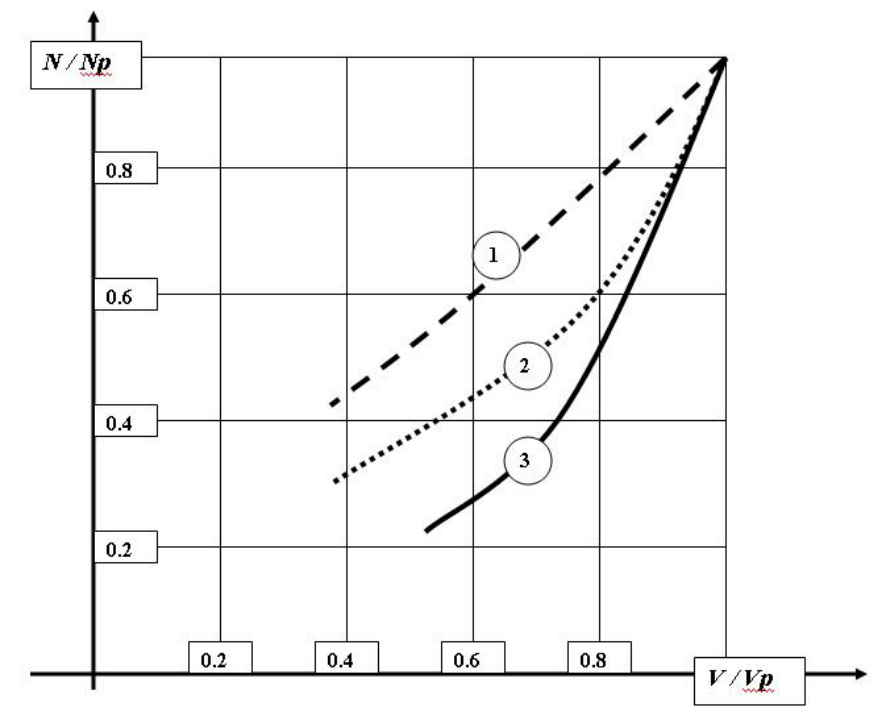
Fig. 1. Power consumption for different control methods
The graphs show that at loads other than 100 %, speed control is the most economical way to apply the control action.
In terms of control loop structure, the most widespread solution is a single-loop scheme with a pulse control unit that, together with a constant-speed actuator, implements a PI control law in pulse mode.
However, it should be noted that the fuel–air ratio and draft control loops are physically coupled through the controlled object. Therefore, when the boiler operates in modulating mode (i.e. with frequent load changes), changing the airflow to maintain the ratio with fuel upsets the balance of material flows. To prevent this, a feed-forward decaying signal from the air controller is introduced (real differentiation of the air controller's output signal).
1.3. Existing furnace draft control equipment
As a rule, small and medium-capacity boilers use the following automation equipment:
Where dynamic coupling between the fuel–air ratio and draft loops is required, the KDS dynamic coupling kit (MZTA) is used.
As we can see, the entire set of equipment is made in Russia. Its longevity is due not only to the conservatism of operating staff but also to the existence of a large market for so-called "surplus stock", whose lifetime is predetermined.
Based on actual prices for new automation equipment, we get the following:
Thus, replacing the instruments (and sooner or later they will fail for good) within the old control scheme will cost about UAH 7,000, without taking a single step towards any economic return.
1.4. Proposed furnace draft control equipment
The upgraded draft control loop is shown in Fig. 2.
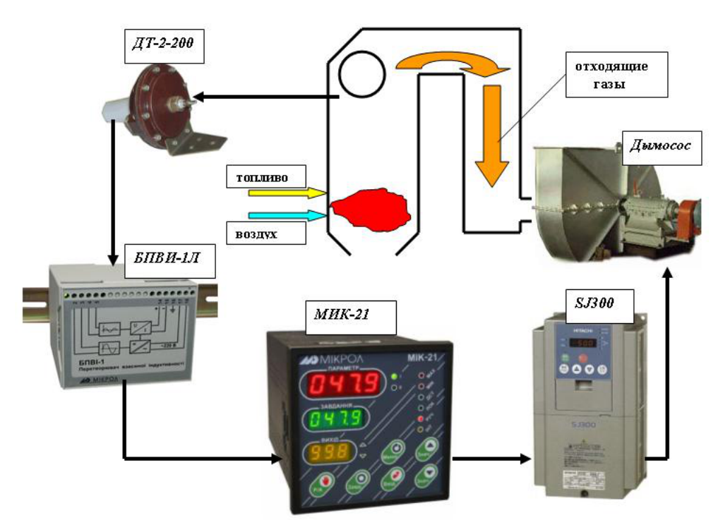
Fig. 2. Upgraded automatic furnace draft control loop
For a quick upgrade of the existing scheme, the DT-2 sensor already used in the loop can be kept. To convert the DT-2 signal into a standard current signal, the BPVI-1L mutual inductance converter with a built-in signal linearization unit (made by Microl) is used. The DT-2 primary winding is powered from the BPVI-1L.
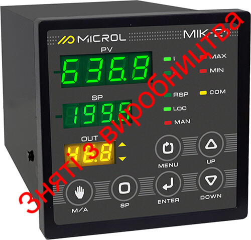
The current signal from the BPVI-1L is fed to the analog input of the MIK-21-05 microprocessor PID controller (Microl). The MIK-21 analog output is connected to the analog input of a variable frequency drive (inverter), for example a Hitachi SJ300. The three-phase inverter output is connected to the supply terminals of the fan's three-phase induction motor (the diagram does not show additional inverter devices such as a line filter, which may be needed depending on drive power). When there is a deviation between the actual and set draft at the MIK-21 input, the controller uses its PID law to change the frequency and voltage supplied to the drive until the deviation is eliminated. The frequency/voltage characteristic type is set when configuring the inverter (for an induced-draft fan — "scalar quadratic").
Programmable digital inputs/outputs on both the MIK-21 and the inverter make it possible to configure various "Manual/Auto" mode options. For example, local manual control can be done with the inverter potentiometer, and changing the state of an inverter digital input hands drive control over to the MIK-21 in "Manual" or "Auto" mode. A signal from the inverter's analog output (either load current or actual output frequency) can be fed to the second MIK-21 input.
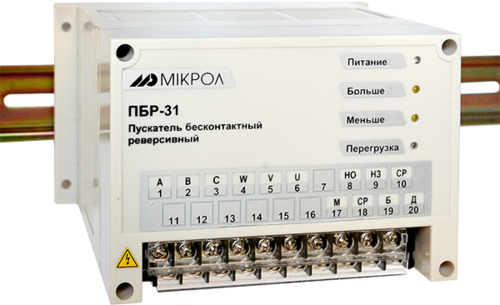
For a step-by-step transition from the old to the new draft control scheme, the design features of the MIK-21 can be used creatively — it contains both pulse and analog PID controllers. If the MIK-21 digital outputs D1 ("More") and D2 ("Less") are connected to the inputs of a PBR-3A starter (PBR-2M for single-phase MEO actuators) using the starter's internal 24 V supply, it is possible at any time to switch back to the old control scheme based on the MIK-21. To do this, it is enough to reconfigure the MIK-21 PID controller structure with the front-panel buttons (and change the settings). Thus, during the transition period the MIK-21 controller is connected to both control loops at once.
The MIK-21 was chosen as the controller for the following interrelated reasons:
As for using a variable frequency drive, one can repeat a phrase found on the Internet: "if there are good reasons, you don't use a frequency converter; if there are no reasons, you use one by default." A scalar voltage/frequency characteristic is sufficient for controlling an induced-draft fan. This is worth keeping in mind when choosing an inverter, since the price difference between vector and scalar types is about 30 %, and not all companies on the Ukrainian market supply inverters, for example of 30 kW, with a scalar characteristic only (Hitachi does). Hitachi inverters lead the Ukrainian market in terms of price/quality ratio.
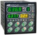
An even more advanced boiler control system can be built with the Microl MIK-51 controller. The coupling between the ratio and draft control loops was mentioned above. By configuring the fuel–air ratio scheme and the draft control scheme in one device, a dynamic link between changes in airflow and the draft loop can be created by connecting the airflow controller output to the draft controller input through a real differentiation block. One version of such a system, built in the ALFA FBD program editor (used to configure the MIK-51 from a PC), is shown in Fig. 3 (part of the ratio scheme is not shown).
The upgrade costs will be:
Since the MIK-21 costs the same as a new RS29, and the DT-2-50 and BPVI-1L together cost less than a new Sapfir transmitter (let alone a Metran), the main expense is the inverter. Numerous Internet publications on inverter installations show a payback period of about 1 year. The greatest economic effect can be achieved on boilers operating with variable load.
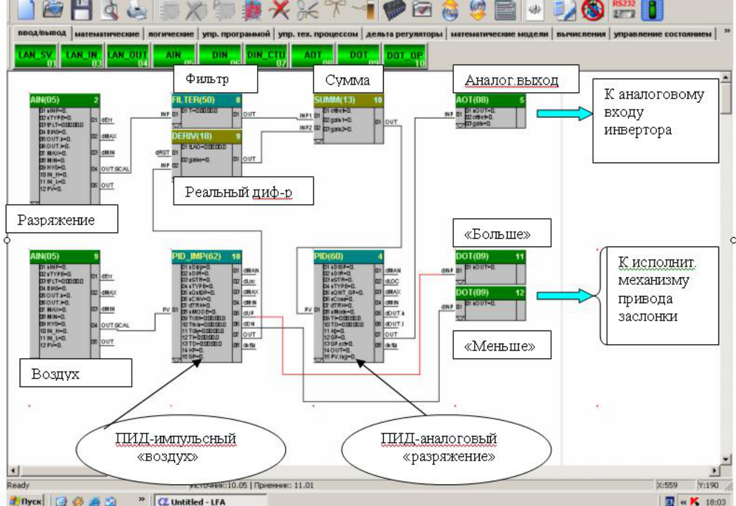
Fig. 3. FBD program of the draft control loops for the MIK-51
Using Microl microprocessor controllers and variable frequency drives in control loops is a modern approach to automation that delivers a significant economic effect through:
For more information about the products mentioned in this article, please contact Microl LLC:
+38 (0342) 502-701
+38 (067) 359-70-90
+38 (095) 092-07-28
sale@microl.ua, microl_zbut@microl.ua, zbutmicrol@gmail.com
www.microl.ua
Technical support:
+38 (0342) 502-702
+38 (067) 704-00-29
+38 (095) 302-37-57
support@microl.ua, supmicrol@gmail.com
Originally published in the all-Ukrainian industry newspaper ElektroTEMA, No. 5, 2006.
Open the booklet / download PDF