







Archive
11.11.2026


 0
 0
 Touch operator panels Weintek
 Meters-indicators
 Controllers (PID, ON/OFF)
 I/O modules

I/O modules
 Spark protection barrier

Spark protection barrier
 Recorders and archivers

Recorders and archivers
 Meters and converters of electrical network parameters

Meters and converters of electrical network parameters
 Counters, timers, tachometers

Counters, timers, tachometers
 Liquid level indicators and regulators

Liquid level indicators and regulators
 Programmed logical controllers

Programmed logical controllers
 Manual signal transmitters

Manual signal transmitters
 Technological signaling devices

Technological signaling devices
 Power supplies

Power supplies
Codesys PLC controllers
Codesys PLC controllers
 Normalizing converters

Normalizing converters
Galvanic isolation and branching blocks
Galvanic isolation and branching blocks
 Communication interface converters and amplifiers

Communication interface converters and amplifiers
 Analytical instruments

Analytical instruments
 Switching blocks

Switching blocks
Control and protection units
Control and protection units
 GSM communication routers / modems

GSM communication routers / modems
Upgrading Recorders and Control Systems at CS-39 of the Urengoy–Pomary–Uzhhorod Pipeline
Archive
11.11.2026
Author
V. V. Pavlyk, I. M. Vovk, V. Y. Vyhodovaniuk, Bohorodchany Line Production Department of Main Gas Pipelines
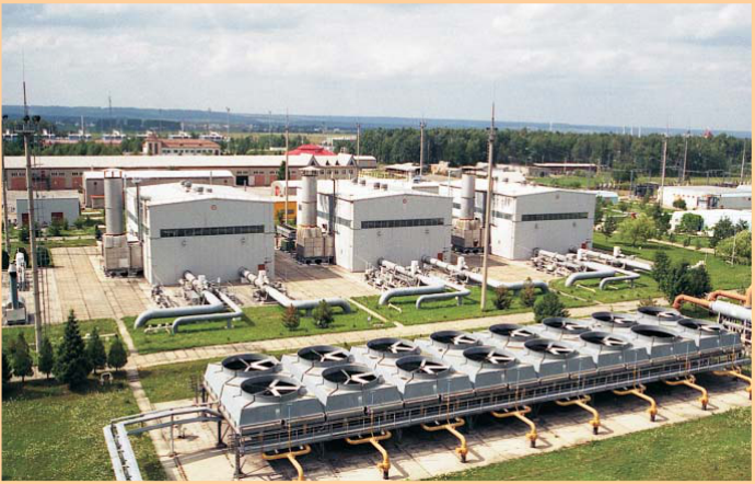
Compressor station No. 39 of the Urengoy–Pomary–Uzhhorod pipeline (Fig. 1) was commissioned in 1983. Its automation equipment, in terms of components and design, corresponds to the level of the early 1980s. Since the replacement of automatic control systems with modern ones has not yet begun at similar compressor stations of Ukrtransgaz with GTK-25I units, this article describes the technical solutions developed by the Instrumentation and Control (I&C) Service of the Bohorodchany Line Production Department to upgrade the most worn-out and obsolete automation systems.
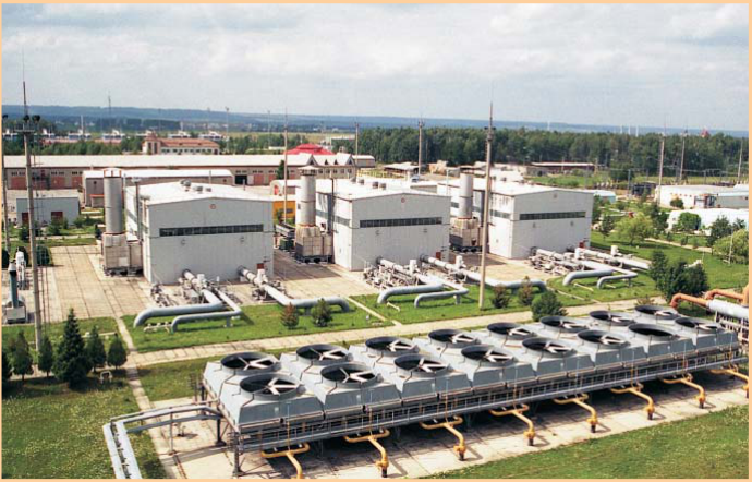
Fig. 1. General view of CS-39, Urengoy–Pomary–Uzhhorod pipeline
The unit and station-wide control panels of CS-39 used SER and LINAX electromechanical chart recorders to monitor and record the main process parameters. After 25 years of operation they had become worn out and obsolete. Worn recorder parts need replacing, and the recorders also require daily maintenance: cleaning the pens, replacing ink, changing charts and so on.
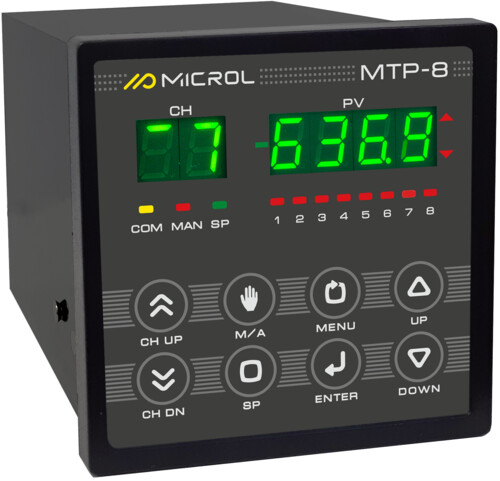
The I&C staff replaced the recorders with a microprocessor-based system for collecting and recording unit and station-wide process parameters, built on four MTR-8 microprocessor controllers made by Microl (Fig. 2). Since the MTR-8 can operate as an 8-channel meter, this scheme records all the process parameters previously wired to the chart recorders with twice the accuracy, and also monitors additional important data:
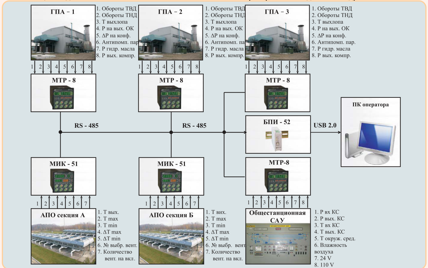
Fig. 2. Structure of the data acquisition system
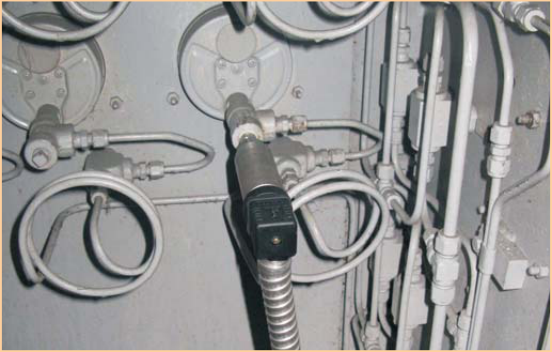
Fig. 3. Hydraulic oil pressure transmitter
Data collected by the MTR-8 instruments is transmitted via RS-485 to the shift engineer's PC at the compressor station, where the Visual Intellect software package displays it on the corresponding mimic diagrams (Figs. 4, 5) and trend charts (Figs. 6, 7).
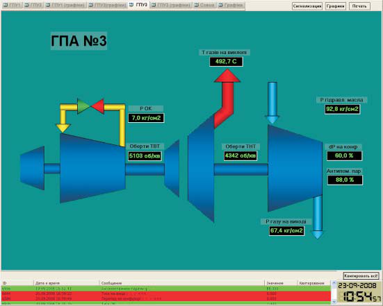
Fig. 4. Mimic diagram of GTK-25I GCU No. 3
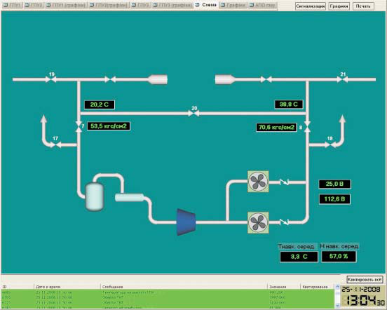
Fig. 5. Station-wide mimic diagram
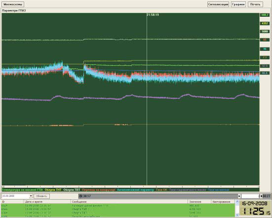
Fig. 6. Trend charts of GTK-25I GCU No. 3 parameters
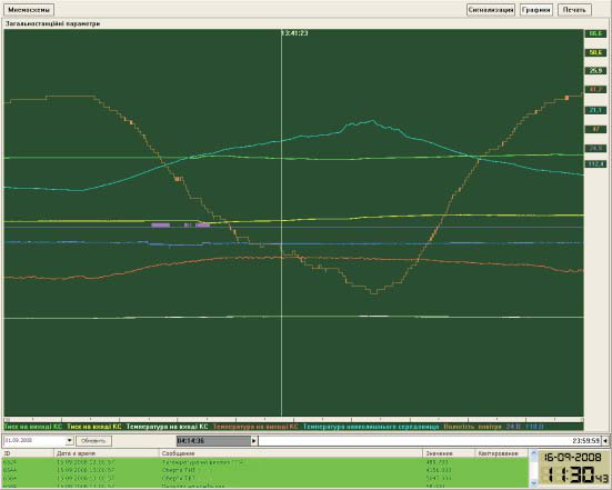
Fig. 7. Trend charts of station-wide parameters
This improvement saves money on new chart recorders (imported equivalents cost an order of magnitude more than MTR-8 instruments), eliminates charts and ink, and makes it possible to display, record and archive data and analyze abnormal situations at the compressor station far better and more accurately, in line with modern requirements.
The fans of the gas air cooling units at CS-39 were controlled by German-made Logistat controllers, built on components equivalent to the Soviet-era KS573RF2 memory chip. In operation, the Logistat controllers proved unreliable: the control program often became corrupted, especially during supply voltage fluctuations, so specialists from the Tekhdiagaz research and engineering center had to rewrite the controllers' ROMs every year. The I&C staff of the Bohorodchany Line Production Department proposed replacing the obsolete Logistat controllers with modern Microl MIK-51 microprocessor controllers (Fig. 8) and integrating them into the existing MTR-8 data acquisition system (Fig. 2).
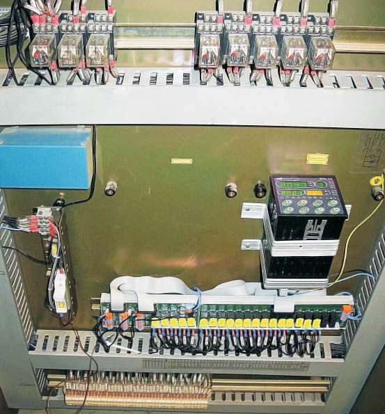
Fig. 8. MIK-51 controller installed in the gas air cooler control panel
The air cooler control program was loaded into the MIK-51 controllers using the ALFA FBD program editor and fully reproduces the Logistat control algorithm. The shift engineer additionally receives on the PC the gas temperature at the outlet of each air cooler section and important MIK-51 operating parameters: the minimum and maximum control setpoints, the number of the fan from which the start-up sequence begins, the number of fans commanded to start, and so on (Fig. 9). To keep the standard panel indicator showing the number of running fans, an electronic encoder board was developed that converts the number of running fans in each air cooler section into binary-coded decimal.
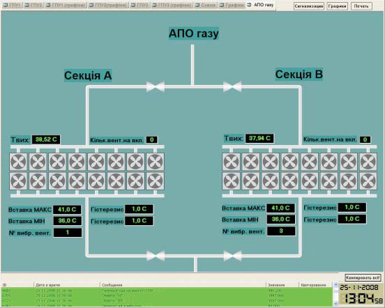
Fig. 9. Gas air cooler mimic diagram
Thus, Ukrainian-made microprocessor instruments and software make it possible to bring process parameter recording and local automatic control systems at compressor stations with GTK-25I units on the Urengoy–Pomary–Uzhhorod pipeline up to modern standards.
For more information about the products mentioned in this article, please contact Microl LLC:
+38 (0342) 502-701
+38 (067) 359-70-90
+38 (095) 092-07-28
sale@microl.ua, microl_zbut@microl.ua, zbutmicrol@gmail.com
www.microl.ua
Technical support:
+38 (0342) 502-702
+38 (067) 704-00-29
+38 (095) 302-37-57
support@microl.ua, supmicrol@gmail.com
Originally published in Truboprovodny Transport (Pipeline Transport) magazine, No. 4(54), November–December 2008.
Open the booklet / download PDF