








Archive
11.11.2026


 0
 0
 Touch operator panels Weintek
 Meters-indicators
 Controllers (PID, ON/OFF)
 I/O modules

I/O modules
 Spark protection barrier

Spark protection barrier
 Recorders and archivers

Recorders and archivers
 Meters and converters of electrical network parameters

Meters and converters of electrical network parameters
 Counters, timers, tachometers

Counters, timers, tachometers
 Liquid level indicators and regulators

Liquid level indicators and regulators
 Programmed logical controllers

Programmed logical controllers
 Manual signal transmitters

Manual signal transmitters
 Technological signaling devices

Technological signaling devices
 Power supplies

Power supplies
Codesys PLC controllers
Codesys PLC controllers
 Normalizing converters

Normalizing converters
Galvanic isolation and branching blocks
Galvanic isolation and branching blocks
 Communication interface converters and amplifiers

Communication interface converters and amplifiers
 Analytical instruments

Analytical instruments
 Switching blocks

Switching blocks
Control and protection units
Control and protection units
 GSM communication routers / modems

GSM communication routers / modems
Archive
11.11.2026
Author
Valerii Dykhnilkin, Microl LLC
E-mail: asutp@microl.ua
A single compact multifunctional MIK-51 programmable controller can automate a fairly complex, typical food industry process unit.
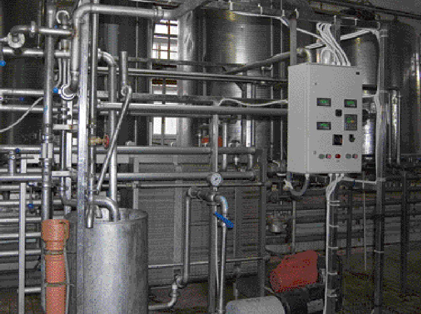
What is a quality product? What do we mean by quality as such? If you think "by the book", a precise definition can always be found in the national DSTU standards: quality means that product characteristics meet the requirements set for them. In the food industry, producing quality products is a particularly pressing issue. In this article we look at some of the finer points of dairy production — specifically, milk pasteurization.
An important factor affecting the quality of milk and dairy products is heat treatment (pasteurization). Pasteurization takes place at a specific temperature (from +63 °C up to near boiling point), which the automation system must maintain with fairly high accuracy (in most cases ±1–5 °C). In the simplest arrangement, milk is heated with steam in a dedicated pasteurizer heat exchanger to the required temperature, held for a certain time and then sent on for further processing. In practice, however, the milk temperature in such an arrangement will "wander" over a rather wide range, which will inevitably affect the quality of the final product.
The reason is that the steam supply from the boiler house to the unit will be uneven, since the intermediate link in this chain is most likely a steam header that also feeds other consumers. The steam pressure in the main changes, and as a result so does the milk temperature. Fast-acting control loops will not help here.
The way out is to add an intermediate stage in the form of another heat exchanger. The steam then heats water, and the water in turn heats the milk in the pasteurizer. This creates a kind of buffer that adds inertia to the system. Such a loop is much easier to automate, whether with conventional controllers or with microcontrollers.
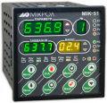
This article describes a milk pasteurization loop that has been operating at the Ivano-Frankivsk dairy plant for more than two years. The automation system is built around the MIK-51 (Fig. 1), a compact multifunctional programmable controller made by Microl. The controller program is created in the ALFA FBD program editor, which was described in Mir Avtomatizatsii No. 5/2008, pp. 24–26.
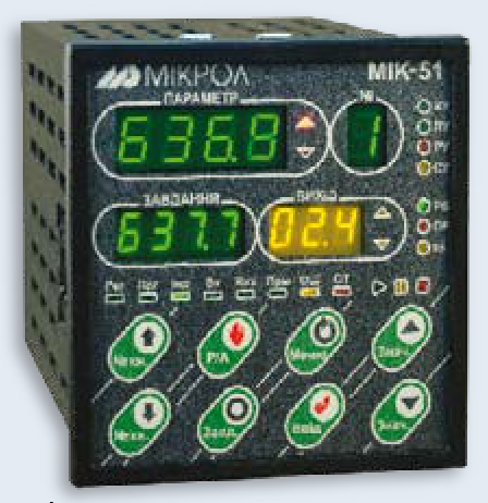
Fig. 1. MIK-51 compact multifunctional programmable controller
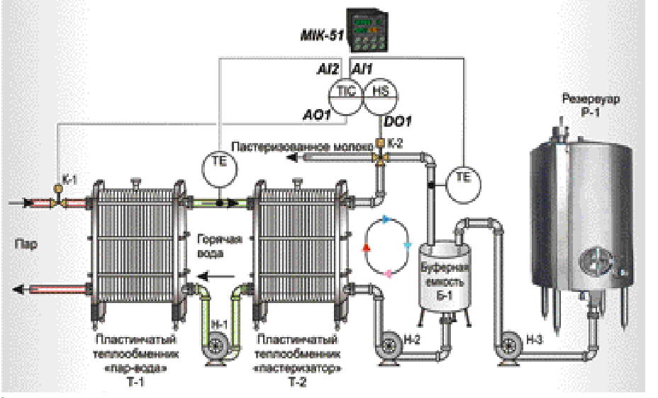
The structure of the milk pasteurization loop is shown in Fig. 2. Pump N-3 feeds milk from tank R-1 into buffer tank B-1, from which pump N-2 delivers it to pasteurizer heat exchanger T-2. If the milk temperature at the pasteurizer outlet is between +88 and +98 °C, the automation must switch ring valve K-2 to position "1", in which the final product (pasteurized milk) leaves the unit. If the product temperature is above or below the normal range, the valve automatically switches to position "0" and the milk returns to buffer tank B-1 for another pass through the pasteurizer.
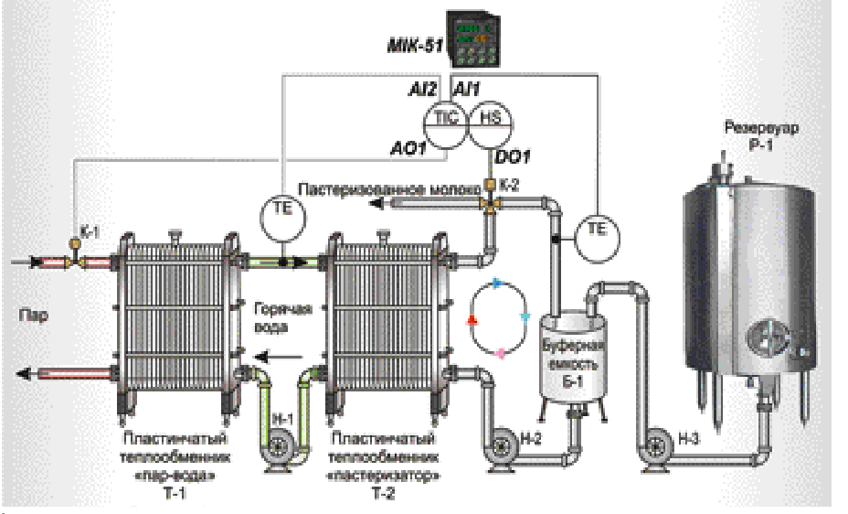
Fig. 2. Structure of the milk pasteurization loop
A series loop is used to heat the milk to the required temperature in the pasteurizer. It works as follows. Steam supplied to the unit enters the steam–water heat exchanger (T-1) and transfers heat to water circulating in a closed loop: pump N-1 — heat exchanger T-1 — pasteurizer T-2 — pump N-1. The water in turn heats the milk in pasteurizer T-2. The degree of heating is determined by the position of control valve K-1 on the steam supply line to heat exchanger T-1.
The automatic control system for this loop has to take many details into account. Above all, accurate and fast control of the milk temperature at the pasteurizer outlet cannot be achieved with simple single-loop PID control, because of the inertia of a system of two heat exchangers connected in series.
This system is a classic case for cascade control. Cascade control is used for loops that have a large transport delay in the control channel and in which an intermediate variable with lower inertia can be measured.
In this case, the optimal solution is to control the milk temperature by changing the steam supply to heat exchanger T-1, taking into account the water temperature at the inlet of pasteurizer T-2. An example of a cascade control loop is shown in Fig. 3.
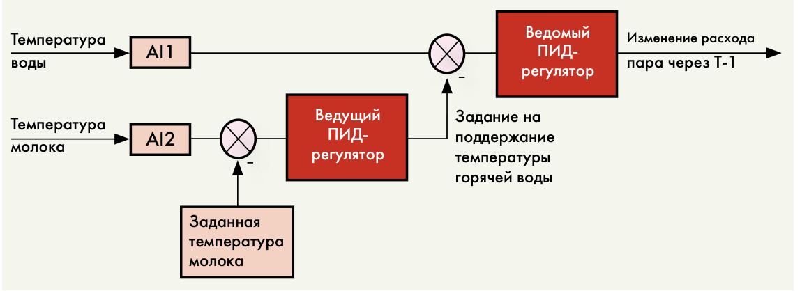
Fig. 3. Example of a cascade control loop
The controller output must also be limited so that valve K-1 opens gradually — ideally following a specified curve.
In addition, the control system must respond correctly to emergencies: a broken sensor line for steam or water temperature, emergency overheating of milk or water, or the water temperature at the pasteurizer inlet rising faster than the set rate.
All of these requirements are easily met by automating the unit with a MIK-51 controller.
To include the controller in the control loop, 2 analog inputs, 1 analog output and 1 digital output are needed. The milk temperature sensor at the pasteurizer outlet is connected to analog input AI1, and the water temperature sensor at the outlet of heat exchanger T-1 to input AI2. Digital output DO1 sets the position of ring valve K-2. The pneumatic actuator positioning valve K-1 on the steam line to heat exchanger T-1 is connected to the controller's analog output AO1 via an electro-pneumatic converter.
Fig. 4 shows a sample FBD program for the controller created in the ALFA editor. The core of the program is the PID_CAS(61) cascade PID controller block (Fig. 5). The block has 2 inputs: PV.M (master controller input) and PV.S (slave controller input).
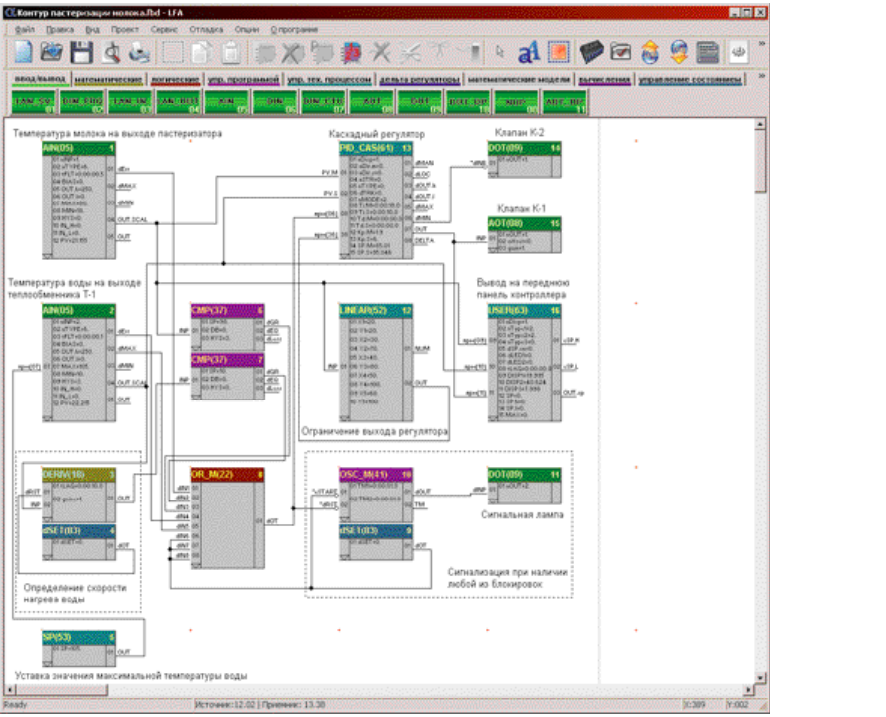
Fig. 4. Sample FBD program for the controller created in the ALFA editor
Input PV.M is connected to the OUT.SCAL output of analog input block No. 1, AIN(05), so the milk temperature after the pasteurizer is fed to the master PID controller. Input PV.S is connected to the corresponding output of analog input block No. 2, which feeds the water temperature after heat exchanger T-1 to the slave PID controller. The controller output goes to analog output No. 1 (block AOT(08)) and to the "OUTPUT" display of the first indicator panel (block USER(63)). In addition, if the temperature falls below the set limit, a logical "1" appears at the dMIN output of the controller block; it is inverted and sends "0" to digital output 1 of the controller, which returns the milk to buffer tank B-1.
The controller output is limited by the LINEAR(52) piecewise-linear function block.
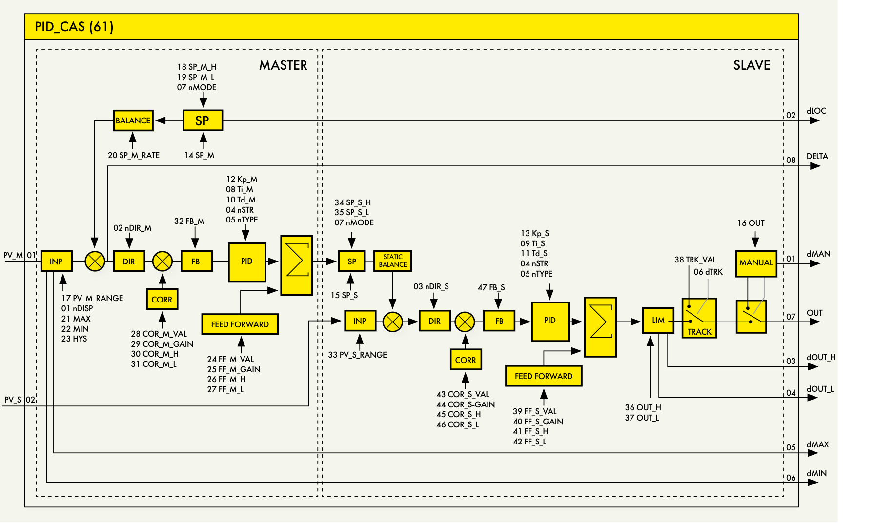
Fig. 5. Internal structure of the cascade PID controller
The water heating rate is determined by the DERIV(18) differentiation block. The rate is compared with the set value (10 °C/s) in comparator CMP(37). If the set value is exceeded, a logical "1" appears at the comparator's dGR output and is fed to the multi-input OR block OR_M(22); this ultimately makes the controller close valve K-1 fully and triggers a light alarm. The other emergency protection loops work in the same way (broken temperature sensor line, milk overheating above 98 °C and water above 105 °C).
The alarm for any active interlock is provided by the OSC_M(41) multivibrator function block: on a high logic signal from the OR block output, it sends 1 to digital output DO2 (block DOT(09)) for 1 s, followed by a 1 s pause.
In addition to the controller output, the first indicator panel also shows the milk temperature ("PARAMETER" display) and the water temperature ("SETPOINT" display).
As you can see, a single controller was enough to automate a fairly complex, typical food industry process unit. And if a reader wants to adjust something in this example or add new functions, the author will consider his task accomplished. After all, the example does not cover every nuance. The program is only a template and a guide to action, not "the answer peeked at the back of the textbook". Each specific case calls for an individual approach to programming the device.
To sum up, the MIK-51 is genuinely easy to program and convenient to operate. If necessary, the controller can be integrated into any SCADA system that supports the Modbus RTU protocol. In addition, the device and its application software are well documented, which end users are sure to appreciate.
The MIK-51 controller is a configurable product: the user selects the required set of modules and units according to the number and type of input and output signals. Depending on the configuration ordered, the controller can have 4 analog inputs (4AI), up to 19 digital inputs (19DI), up to 4 analog outputs (4AO) and up to 21 digital outputs (21DO).
The device has built-in self-diagnostics: fault alarms and identification, alarms when signals go out of range, RAM failures, network communication errors and more.
The controller is programmed from the front-panel keys or via the interface using dedicated software — the ALFA visual FBD program editor. The editor has a built-in program debugger, logical program state checking, program documentation and printing, table view of the program and more.
The MIK-51 contains a function block library sufficient for fairly complex automatic control and programmed logic control tasks. The library has the following sections:
For more information about the products mentioned in this article, please contact Microl LLC:
+38 (0342) 502-701
+38 (067) 359-70-90
+38 (095) 092-07-28
sale@microl.ua, microl_zbut@microl.ua, zbutmicrol@gmail.com
www.microl.ua
Technical support:
+38 (0342) 502-702
+38 (067) 704-00-29
+38 (095) 302-37-57
support@microl.ua, supmicrol@gmail.com
Originally published in Mir Avtomatizatsii (World of Automation) magazine, December 2008.
Open the booklet / download PDF