











Archive
11.11.2026


 0
 0
 Touch operator panels Weintek
 Meters-indicators
 Controllers (PID, ON/OFF)
 I/O modules

I/O modules
 Spark protection barrier

Spark protection barrier
 Recorders and archivers

Recorders and archivers
 Meters and converters of electrical network parameters

Meters and converters of electrical network parameters
 Counters, timers, tachometers

Counters, timers, tachometers
 Liquid level indicators and regulators

Liquid level indicators and regulators
 Programmed logical controllers

Programmed logical controllers
 Manual signal transmitters

Manual signal transmitters
 Technological signaling devices

Technological signaling devices
 Power supplies

Power supplies
Codesys PLC controllers
Codesys PLC controllers
 Normalizing converters

Normalizing converters
Galvanic isolation and branching blocks
Galvanic isolation and branching blocks
 Communication interface converters and amplifiers

Communication interface converters and amplifiers
 Analytical instruments

Analytical instruments
 Switching blocks

Switching blocks
Control and protection units
Control and protection units
 GSM communication routers / modems

GSM communication routers / modems
Computerized Coolant Level Monitoring in the Expansion Tanks of GTK-10I Gas Compressor Units
Archive
11.11.2026
Author
V. V. Pavlyk, Z. Y. Kotsur, Instrumentation and Control Service, Bohorodchany Line Production Department of Main Gas Pipelines
The Speedtronic automatic control systems installed on the GTK-10I gas compressor units (GCUs) of the Soyuz pipeline in the 1970s have a number of drawbacks, including insufficient information and the use of contact-type sensors. This article describes how the Instrumentation and Control (I&C) Service of the Bohorodchany Line Production Department improved visualization and set up early-warning alarms and archiving of important process parameters using its own resources.
GTK-10 turbine unit
According to the design, the coolant expansion tank of the GTK-10I turbine unit is fitted with a sight glass level gauge (Fig. 1, item 1) for visual monitoring and a 71WL contact-type low antifreeze level switch (Fig. 1, item 2). When the coolant level drops below the set limit (100 mm below the center line of the expansion tank), the 71WL low-level relay signal shuts down the cooling system pumps and turns on an alarm on the turbine control panel.
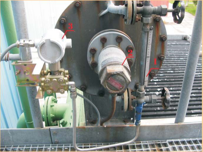
Fig. 1. Coolant expansion tank: 1 — sight glass level gauge; 2 — 71WL low-level switch; 3 — Honeywell STD110 differential pressure transmitter
With the existing alarm system, if a leak develops in the antifreeze circuit, operating personnel do not have enough time to prevent an emergency shutdown of the GCU: within 10–15 minutes of the cooling pumps stopping, the lube oil temperature in the turbine header rises to the +65 °C trip setpoint.
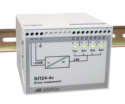
The I&C staff of the Bohorodchany Line Production Department additionally installed a Honeywell STD110 differential pressure transmitter (Fig. 1, item 3), calibrated for 0–250 mm H₂O, on the coolant expansion tank via the drain valve of the sight glass. A cable was run from the transmitter to junction box No. 27. Spare cores of cable No. 028 were used from junction box No. 27 to the DB42 circulation pump control box, and spare cores of cable No. 097 from the DB42 cell to the HB-1 turbine control panel. A BPS-24 power supply was installed in the HB-1 compressor control panel to supply 24 V to the new transmitter (Fig. 2).
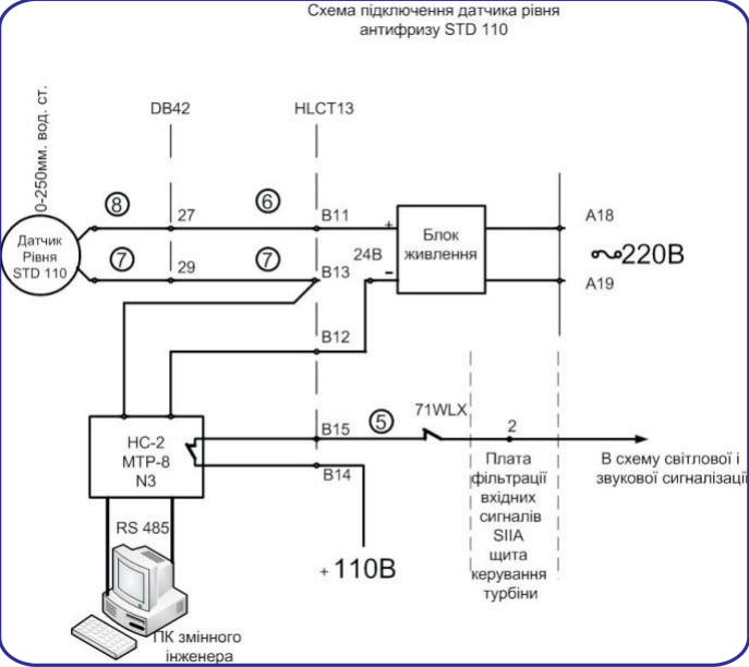
Fig. 2. Wiring diagram of the STD110 antifreeze level transmitter
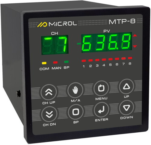
An MTR-8 microprocessor instrument (Fig. 3) was installed in the NS-2 station-wide panel. It converts the transmitter's 4–20 mA analog signal into a digital value, continuously transmits data via RS-485 to the shift engineer's PC and, when the antifreeze level reaches the programmed threshold, issues visual and audible warning signals on the turbine control panel.
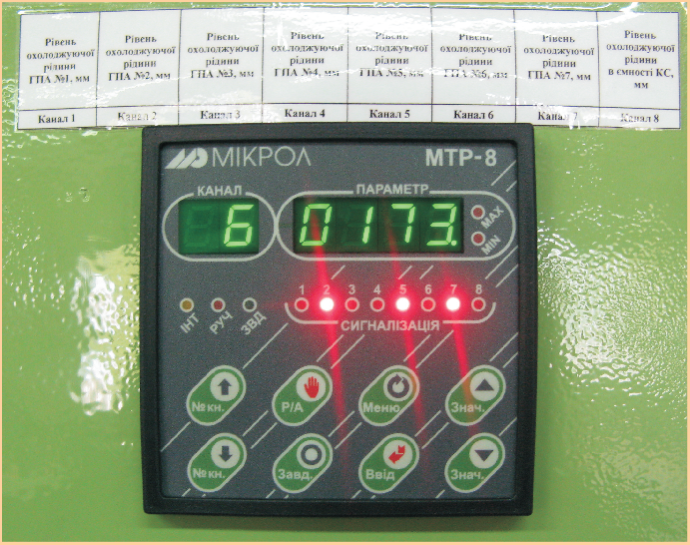
Fig. 3. MTR-8 instrument in the NS-2 station-wide panel
The MIK-Registrator software package on the shift engineer's PC displays the antifreeze levels received from the MTR-8 as bar graphs (Fig. 4) and archives them in digital and graphical form (Fig. 5).
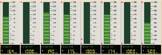
Fig. 4. Antifreeze levels as bar graphs in MIK-Registrator
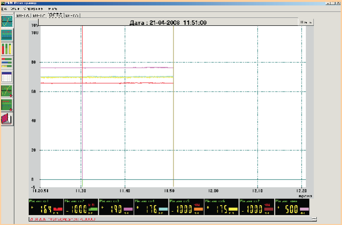
Fig. 5. Archived antifreeze levels in graphical form
The proposed scheme provides digital readings of the coolant level in the GCU expansion tank on the MTR-8 instrument, digital values and a trend on the shift engineer's PC, and a warning signal on the turbine control panel 100 mm above the design setpoint (the trip threshold can be changed during calibration). This allows operating personnel to respond promptly to a leak in the antifreeze circuit — for example, by switching to the standby pump and isolating and repairing the damaged section.
This improvement provides continuous monitoring and archiving of the antifreeze level in the GCU expansion tank and increases measurement accuracy and safety (the design sight glass is located on a process platform 4 m above the ground). Analyzing antifreeze level fluctuations over time makes it possible to check the tightness of the GCU cooling circuit, since the antifreeze heat exchanger is in direct contact with the lube oil, whose pressure during GCU operation is 2 kgf/cm² higher than the coolant pressure.
As of April 2008, computerized antifreeze level monitoring had been set up at the Soyuz CS-21 compressor station of the Bohorodchany Line Production Department on the expansion tanks of GCUs No. 1, 3, 4 and 6 and on the station-wide coolant tank. The I&C Service is currently testing the new Visual Intellect SCADA system for polling MTR-8 instruments, which, if successful, will replace the MIK-Registrator software.
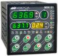
An automatic gas air cooling system is currently being introduced at compressor station CS-39 of the Urengoy–Pomary–Uzhhorod pipeline. The new control system, based on MIK-51 controllers, replaces the previously installed German Logistat system. The MIK-51 continuously monitors gas temperature and automatically controls the air cooler fans, distributing the load evenly between them so that all fans have the same service life. The control system also keeps the air cooling unit running without interruption when one or more fans are switched off, for example for repair.
For more information about the products mentioned in this article, please contact Microl LLC:
+38 (0342) 502-701
+38 (067) 359-70-90
+38 (095) 092-07-28
sale@microl.ua, microl_zbut@microl.ua, zbutmicrol@gmail.com
www.microl.ua
Technical support:
+38 (0342) 502-702
+38 (067) 704-00-29
+38 (095) 302-37-57
support@microl.ua, supmicrol@gmail.com
Originally published in Truboprovodny Transport (Pipeline Transport) magazine, No. 3(53), September–October 2008.
Open the booklet / download PDF