








































Archive
09.11.2026


 0
 0
 Touch operator panels Weintek
 Meters-indicators
 Controllers (PID, ON/OFF)
 I/O modules

I/O modules
 Spark protection barrier

Spark protection barrier
 Recorders and archivers

Recorders and archivers
 Meters and converters of electrical network parameters

Meters and converters of electrical network parameters
 Counters, timers, tachometers

Counters, timers, tachometers
 Liquid level indicators and regulators

Liquid level indicators and regulators
 Programmed logical controllers

Programmed logical controllers
 Manual signal transmitters

Manual signal transmitters
 Technological signaling devices

Technological signaling devices
 Power supplies

Power supplies
Codesys PLC controllers
Codesys PLC controllers
 Normalizing converters

Normalizing converters
Galvanic isolation and branching blocks
Galvanic isolation and branching blocks
 Communication interface converters and amplifiers

Communication interface converters and amplifiers
 Analytical instruments

Analytical instruments
 Switching blocks

Switching blocks
Control and protection units
Control and protection units
 GSM communication routers / modems

GSM communication routers / modems
Archive
09.11.2026
Author
Yevhen Myronenko, foreman of the thermal automation shop, Kremenchuk CHP Plant
This article discusses how to build an automatic control system for boiler superheated steam temperature and the gas–air ratio using modern automation equipment and technologies. The purpose of this control system is to solve today's most pressing task: saving gas and significantly reducing its consumption at facilities such as combined heat and power (CHP) plants, boiler houses and the like. The system requires low implementation costs and pays back quickly. The solution has been implemented as part of an automated system at the Kremenchuk CHP Plant of Poltavaoblenergo OJSC.
The Kremenchuk CHP Plant of Poltavaoblenergo OJSC is one of Ukraine's leading industrial enterprises, generating electricity and heat from the chemical energy of fossil fuel. In 2005 the plant turned 40.
The plant generates electricity (electrical capacity — 255 MW), which is delivered through distribution networks to the power grid and to consumers, as well as heat in the form of superheated steam and network water used to supply the northern industrial hub and the city of Kremenchuk. The plant's thermal capacity is provided by four TGM-84 steam boilers with an output of 420 t/h each and two hot-water boilers. Its electrical capacity comes from four turbine generators with a total output of 255 MW.
Despite its age, the enterprise is developing dynamically and pays great attention to introducing modern high-tech developments in process control.
In 2004–2005, the automatic control system for superheated steam temperature of TGM-84 boilers No. 1 and 2 was reconstructed on the basis of MIK-51 microprocessor programmable controllers manufactured by Microl LLC (Ivano-Frankivsk). The main task was to replace the vacuum-tube differentiating units (DLT) in the superheated steam temperature control loops, whose magnetic amplifiers had been failing en masse. In total, 10 control loops were reconstructed: TGM-84 boiler No. 2 — injections No. 1, 2, 3, left and right; boiler No. 1 — injections No. 1, 2, left and right (No. 2 is a standby).
Because MIK-51 controllers can be connected to a common process network via the RS-485 interface, a system for visualizing and archiving superheated steam temperature on TGM-84 boilers No. 1 and 2 was put into operation at the end of 2005. This monitoring system makes it possible to monitor all temperature points of the boiler superheaters (platen and convective).
The block diagram of the control system is shown in Fig. 1.
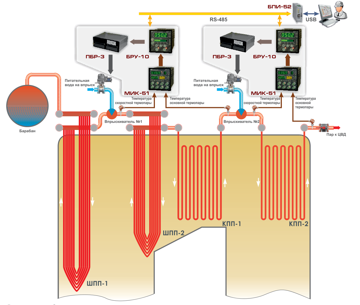
Fig. 1. Block diagram of the control system
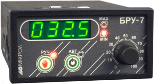
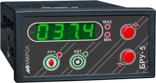
The electrical circuit for controlling the regulating valve together with the actuator is built around the BRU-10 multifunctional manual control unit made by Microl, which performs three functions simultaneously:
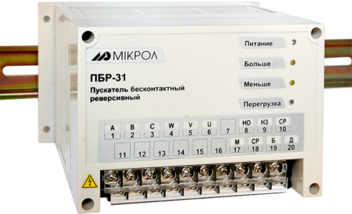
The starting and control equipment comprises a PBR-3A contactless reversing starter, an AP-50 3MT circuit breaker and an MEO-630/25-0.25 actuator with a current output. The regulating element is a KDUM rotary straight-through injection control valve with weld-on connections.
Given the positive experience with Microl controllers, the Kremenchuk CHP Plant plans to use them further in its production process — this time as a GAS–AIR ratio controller. The main drawback of older controller series such as RPIB, R25, RS29 and others is that they cannot automatically control the GAS–AIR ratio along the burner's piecewise-linear characteristic (curve A, Fig. 2). Older series could only control along a straight line (constant ratio, line B), tuned at two reference points (points 1 and 2). Although automatic mode had economic advantages, it still did not fully solve the problem of burning gas in the furnace as economically as possible: there were zones of air deficiency (4–5, 6–2) and air excess (1–4, 5–6). Only at individual operating points (4, 5, 6) was the GAS–AIR ratio ideal and the burner running in its most economical mode.
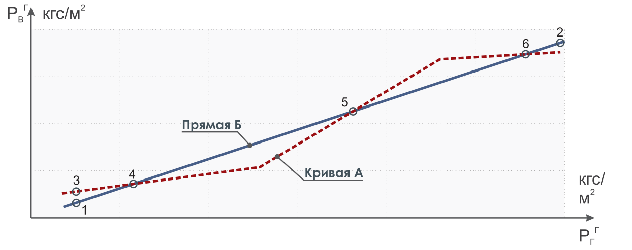
Fig. 2. GAS–AIR ratio chart
To accomplish this task, Microl developed the MIK-25 ratio controller, which can linearize the ratio of two variables over a range using up to 19 reference points. The controller is structured as a two-variable ratio controller that tracks a specified linearization curve. Until now, heat engineers have used 5–6 reference points after burner tests. Even if stricter combustion accuracy requirements lead to the use of 10–12 reference points, the controller's capabilities still exceed what is required.
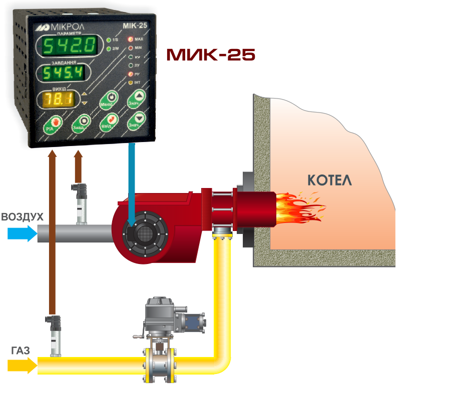
The block diagram of the control system based on the flow ratio controller is shown in Fig. 3.
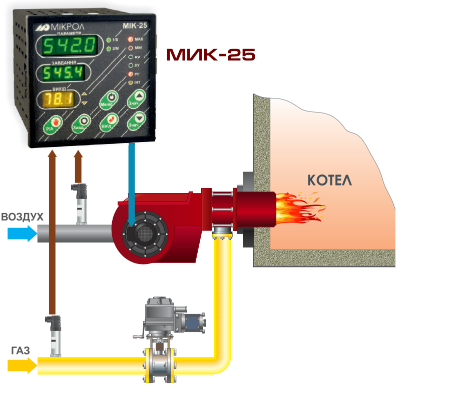
Fig. 3. Block diagram of the flow ratio controller
The MIK-25 controller performs today's most pressing task: reducing gas consumption through new technologies or advanced new equipment.
The MIK-25 has a PID controller structure, and testing and simulation confirmed that it delivers the high control quality expected of it.
In addition to its main purpose, the controller can provide extra service functions:
Since the MIK-25 includes a ratio controller structure, it can serve not only as a GAS–AIR flow ratio controller but also as:
It should also be noted that the control task solved with the MIK-25 can also be implemented on the MIK-51 programmable controller, with more complex structures and control algorithms.
To save gas with Microl equipment, older controllers can be replaced with the following sets:
The existing equipment remains unchanged, and the way it operates stays the same.
Gas consumption can be reduced (i.e. gas saved) by 5–10 % if the old settings were made carefully, and by more if they were not. Before installing new Microl equipment, it is advisable to carry out new, more thorough thermal tests of the burner.
Thus, solving this problem requires neither substantial capital investment nor a long payback period. One solution is to introduce modern process automation systems.
The relatively low cost of automation systems and equipment (the MIK-25 controller costs UAH 1,500), the small amount of implementation work and a payback period of no more than 2–3 months all make it possible to address today's pressing task: saving gas and significantly reducing its consumption at CHP plants, boiler houses and similar facilities.
To help solve this task, the manufacturer's website www.microl.ua provides:
Within a short article, we will not go into the importance of energy saving for the life of the country. We will only note that this problem is acute in many industries, and every enterprise should contribute to solving it!
Gas saving is no longer theory — it is practice!
For more information about the products mentioned in this article, please contact Microl LLC:
+38 (0342) 502-701
+38 (067) 359-70-90
+38 (095) 092-07-28
sale@microl.ua, microl_zbut@microl.ua, zbutmicrol@gmail.com
www.microl.ua
Technical support:
+38 (0342) 502-702
+38 (067) 704-00-29
+38 (095) 302-37-57
support@microl.ua, supmicrol@gmail.com
Originally published in Elektropanorama magazine, No. 1, 2006.
Open the booklet / download PDF