








Archive
18.11.2026


 0
 0
 Touch operator panels Weintek
 Meters-indicators
 Controllers (PID, ON/OFF)
 I/O modules

I/O modules
 Spark protection barrier

Spark protection barrier
 Recorders and archivers

Recorders and archivers
 Meters and converters of electrical network parameters

Meters and converters of electrical network parameters
 Counters, timers, tachometers

Counters, timers, tachometers
 Liquid level indicators and regulators

Liquid level indicators and regulators
 Programmed logical controllers

Programmed logical controllers
 Manual signal transmitters

Manual signal transmitters
 Technological signaling devices

Technological signaling devices
 Power supplies

Power supplies
Codesys PLC controllers
Codesys PLC controllers
 Normalizing converters

Normalizing converters
Galvanic isolation and branching blocks
Galvanic isolation and branching blocks
 Communication interface converters and amplifiers

Communication interface converters and amplifiers
 Analytical instruments

Analytical instruments
 Switching blocks

Switching blocks
Control and protection units
Control and protection units
 GSM communication routers / modems

GSM communication routers / modems
Archive
18.11.2026
Author
Valerii Dykhnilkin, Volodymyr Kapustiak, Microl LLC
E-mail: asutp@microl.ua
In modern process control systems, data acquisition, analysis and processing and the transmission of data and control commands are handled by specialized software — SCADA systems such as Visual Intellect. While each has its own distinctive features, such systems ensure stable operation and improve the overall performance of the processes they control.
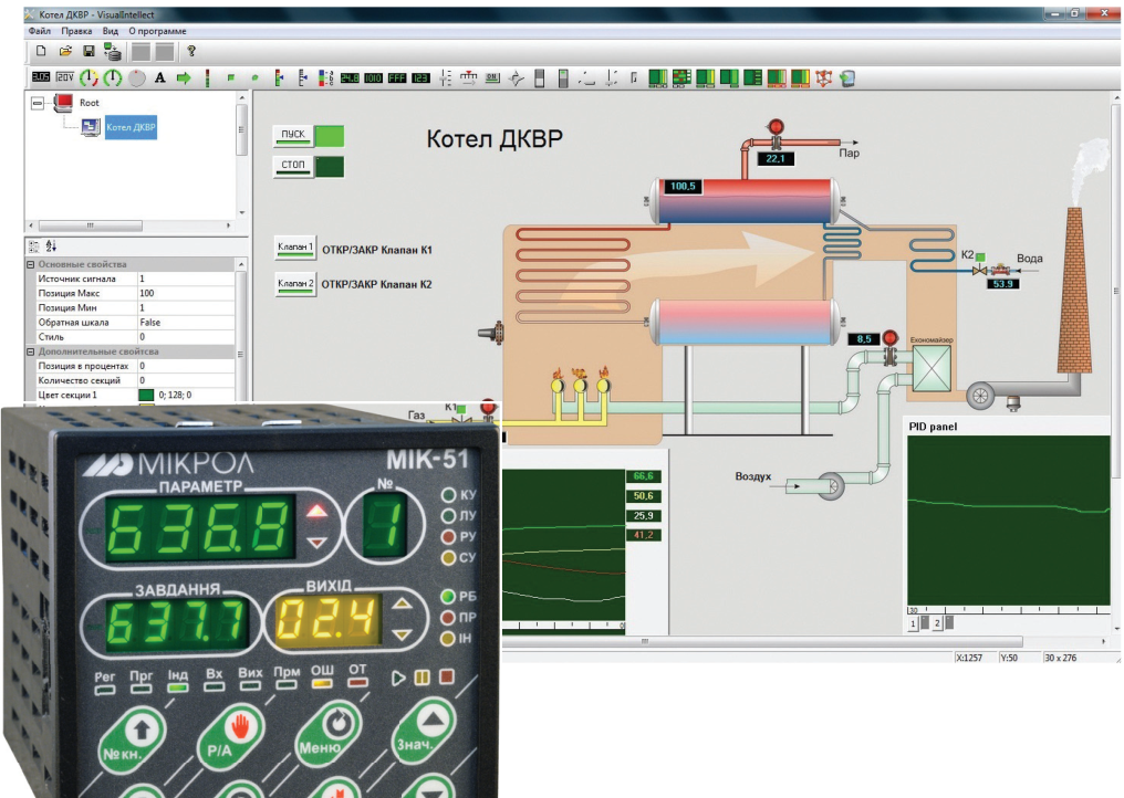
The development of automation equipment today is inseparable from computing. Smart primary sensors, microprocessor indicators, regulators and controllers, operator panels and recorders are all based on specialized microprocessors, and using them is directly linked to the concept of an interface.
Technically, an interface is the set of hardware, software and design means needed for the various functional elements of automated data acquisition and processing systems to interact under conditions defined by a standard, ensuring full compatibility between those elements. In short, an interface is the link between particular components of a system.
Among the many interfaces, the human–machine interface stands somewhat apart. In today's information world it usually means a kind of "layer" between a person and a computer. In process control systems, this interface is one of the main components of specialized software products — SCADA systems.
This article is about the new version of the Ukrainian Visual Intellect SCADA system developed by Microl (Ivano-Frankivsk). Visual Intellect V2.0 (Fig. 1) is a modern, multifunctional, high-performance SCADA system for data acquisition, analysis, processing, transmission and control in process control systems. The new version has taken the best of its predecessor (V1.0) and offers fully stable operation, higher overall performance, a more convenient user interface, extended networking functions, a variety of client–server structures, a modular and scalable architecture, built-in redundancy, a new alarm handling unit, a reporting module and more.
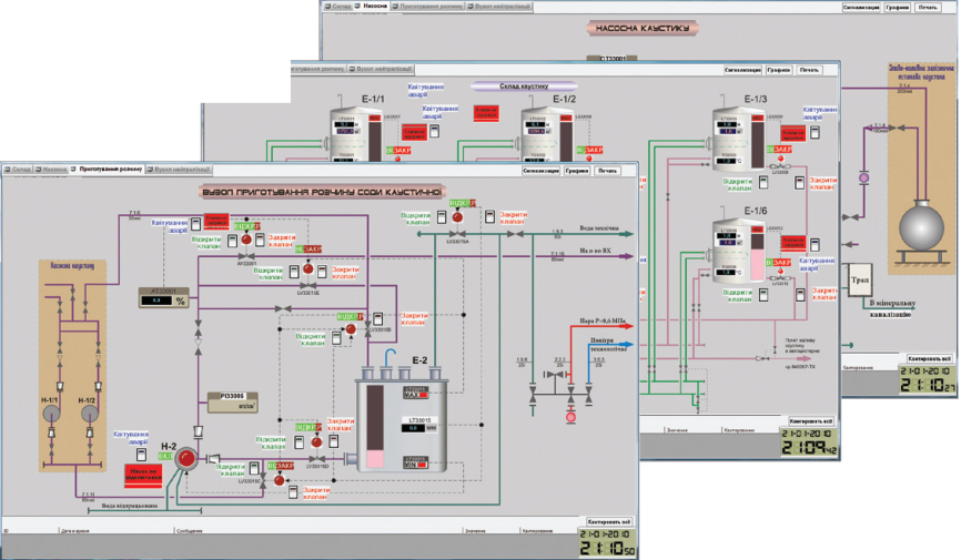
Fig. 1. Visual Intellect SCADA system
As in previous versions, the core of Visual Intellect V2.0 is MNTserver. This application runs as an operating system service and handles the interaction of all software components, so it underwent a number of changes in the new version. Many requests from both system integrators and end users were taken into account.
The core now allocates processor time by priority between tasks running in parallel. In addition, most of the core code has been optimized, which has significantly increased the performance of the whole SCADA system: I/O point values update without slowdown even when a project has thousands or tens of thousands of them.
Visual Intellect V2.0 supports all Microl microprocessor instruments. Third-party devices (for example, Siemens and Omron) can also be connected via the Modbus RTU protocol.
Visual Intellect makes it possible to implement a variety of distributed client–server architectures when deploying a process control system (Fig. 2). For example, a local network linking the upper-level hardware may include a server and one or more clients. On the server, displays for the clients are configured with the display program, in one of two ways: each client gets its own display, or several clients work with one display.
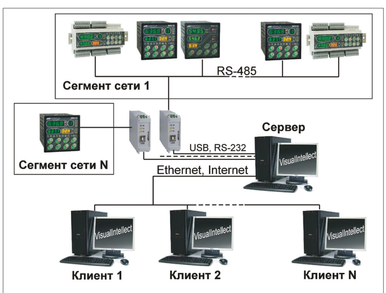
Fig. 2. Distributed client–server architecture
Visual Intellect V2.0 can be used at large enterprises that need SCADA at several sites within one process or plant, with data links between them and global dispatch monitoring. For each autonomous automation site, a separate logical database is created on a server and linked to clients. The upper-level local or global networks of each site are joined into a common network, directly or through intermediate devices. Importantly, standalone clients not strictly tied to any particular site can be created on the common network; their displays can use data from any logical database whose server is on that network.
The Visual Intellect V2.0 distribution includes a large number of ready-made templates describing the hardware and software of a process control system (Fig. 3). There is no need to describe device I/O point structures or the structure and topology of upper-level local and global networks by hand. Ready-made template files describing the internal structure of every Microl microprocessor instrument are provided; the user simply imports the required template into the SCADA logical database and binds it to the relevant process variables. Third-party devices are added and network structures described in the same way (standard templates are available for this too).
Templates for a specific device can also be created manually using a dedicated editor included with Visual Intellect V2.0.
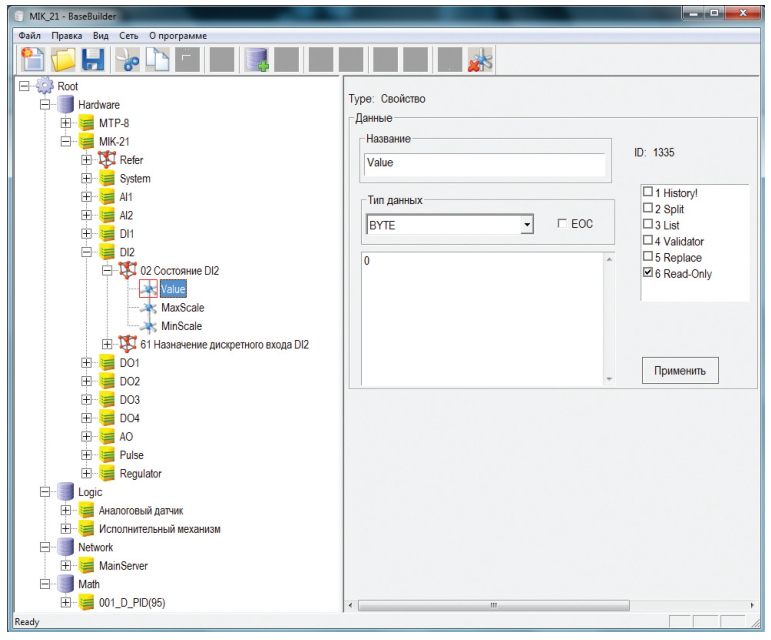
Fig. 3. Ready-made template for the MIK-21 controller
Reliability is an important characteristic of a SCADA system, determined above all by the reliability of its software core, the logical database. In Visual Intellect this is achieved by adding a backup server to the control system hardware (Fig. 4). During deployment the logical database is created on the main server, and in operation it is used on all servers of the system.
Once the SCADA system is in service, the main server acts as the network master, sending and receiving data, while the backup server listens to the network. If an abnormal situation or a main server failure occurs, control passes to the backup server. Not just one but several backup servers can be connected; the order in which they take over is set in the network connection parameters of the SCADA server database.
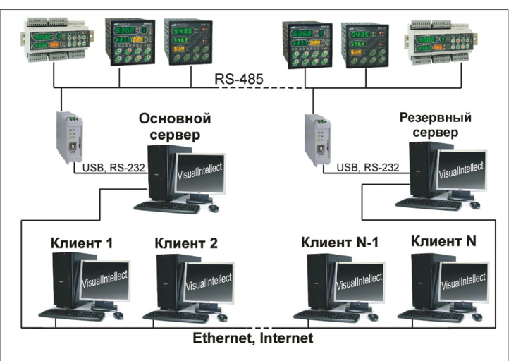
Fig. 4. Visual Intellect hardware platform with a backup server
The SCADA system's response to process upsets is handled by a dedicated alarm and emergency protection manager, whose algorithm cyclically checks process variables against their permissible limits. There are two types of limits: operating limits (low and high) and emergency limits (low and high). Operating limits notify the operator of deviations from normal operation. Emergency limits notify the operator of emergency conditions and are used in emergency protection schemes for process equipment.
The ReportMaker reporting module (Fig. 5) creates reports for any required period on selected archived process variables (tags), in a form convenient for the user. Its wide capabilities come from a built-in command interpreter whose command set can process not only data from the Visual Intellect archive but also any other numerical variables specified by the user.
ReportMaker provides:
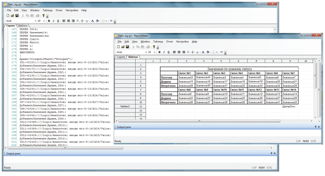
Fig. 5. ReportMaker reporting module
At the time of publication, Visual Intellect V2.0 was available in 3 editions:
The editions differ only in the number of I/O points: Basic and Standard provide full functionality of all Visual Intellect V2.0 Professional components.
The Basic edition can be used both to automate small facilities and for training; at the time of publication it could be downloaded free of charge from the Microl website and used on any number of sites without registration or a license. The Standard edition is intended for operator workstations at most facilities in various industries: 500 I/O points are quite enough to control one or several workshops at once. The Professional edition has no I/O point limit and is aimed at plant-wide centralized SCADA.
Note that the I/O point limit applies only to the server part of Visual Intellect. The client part is unlimited and free of charge.
Current software versions and terms of use are available in the Software section at www.microl.ua.
For more information about the products mentioned in this article, please contact Microl LLC:
+38 (0342) 502-701
+38 (067) 359-70-90
+38 (095) 092-07-28
sale@microl.ua, microl_zbut@microl.ua, zbutmicrol@gmail.com
www.microl.ua
Technical support:
+38 (0342) 502-702
+38 (067) 704-00-29
+38 (095) 302-37-57
support@microl.ua, supmicrol@gmail.com
Originally published in Mir Avtomatizatsii (World of Automation) magazine, No. 2, May 2010.
Open the booklet / download PDF