







Archive
16.11.2026


 0
 0
 Touch operator panels Weintek
 Meters-indicators
 Controllers (PID, ON/OFF)
 I/O modules

I/O modules
 Spark protection barrier

Spark protection barrier
 Recorders and archivers

Recorders and archivers
 Meters and converters of electrical network parameters

Meters and converters of electrical network parameters
 Counters, timers, tachometers

Counters, timers, tachometers
 Liquid level indicators and regulators

Liquid level indicators and regulators
 Programmed logical controllers

Programmed logical controllers
 Manual signal transmitters

Manual signal transmitters
 Technological signaling devices

Technological signaling devices
 Power supplies

Power supplies
Codesys PLC controllers
Codesys PLC controllers
 Normalizing converters

Normalizing converters
Galvanic isolation and branching blocks
Galvanic isolation and branching blocks
 Communication interface converters and amplifiers

Communication interface converters and amplifiers
 Analytical instruments

Analytical instruments
 Switching blocks

Switching blocks
Control and protection units
Control and protection units
 GSM communication routers / modems

GSM communication routers / modems
Archive
16.11.2026
Author
Valerii Dykhnilkin, Volodymyr Kapustiak, Microl LLC
E-mail: asutp@microl.ua
Anyone who works with computers in one way or another has come across programming. The need to write your own algorithms arises mainly because there are no ready-made software tools for some tasks.
Knowing a programming language and being able to use that knowledge to write a program for a specific task are two different things. Programming as such involves an element of creativity, which forces the author to take an individual approach to each task. This describes very accurately the state of affairs in programming PLCs for industrial process control systems.
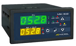
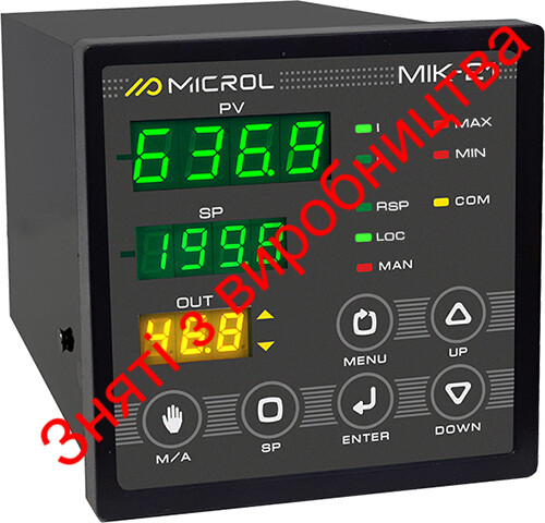
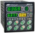
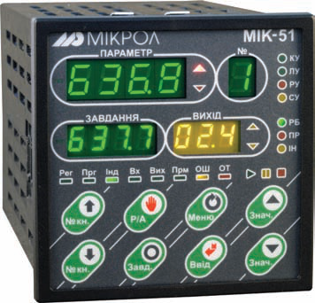
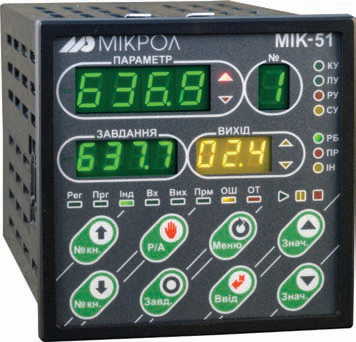
Below we look at programming Ukrainian-made universal MIK-51 controllers from Microl (Ivano-Frankivsk) and their variants (MIK-51N, MIK-52, MIK-52N). MIK-51 programming has been discussed in Mir Avtomatizatsii more than once. The controller's use was shown with specific examples: controlling a milk pasteurization unit (No. 6/2008) and timber drying (No. 1-2/2009). A brief description was also given of all PID algorithms — no fewer than 7 types — included in the controller's algorithm library (No. 3-4/2009).
This article takes a slightly different approach and offers templates on which you can base your own programs for various continuous control and discrete control loops.
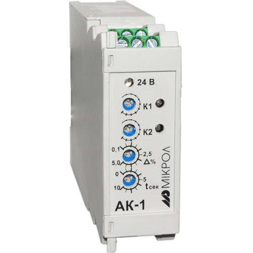
The strong interest in the MIK-51 is due above all to the device's versatility on the one hand and its low price on the other. In addition, an expansion module (more than 10 types are available) can be installed in the controller to increase the number of available inputs/outputs.
In practice, a process often requires not only keeping the controlled variable close to the setpoint with a certain accuracy, but also changing the setpoint itself according to a program. Say a furnace must be heated to temperature No. 1, held there for a certain time, then raised to temperature No. 2, held again and finally cooled down gradually. All of this runs in cycles, with a choice of one of several setpoint-versus-time profiles.
Creating such a PID control program for the MIK-51 is not difficult. Fig. 1 shows one possible version of a "Programmed PID controller". Despite its seemingly bulky appearance, it is easy to understand and to adapt to a specific process.
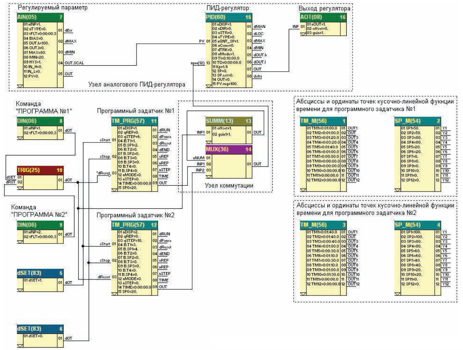
Fig. 1. "Programmed PID controller" program template
The program includes an analog PID controller section (function blocks No. 7, 15 and 17), a switching section (blocks No. 13 and 14) and a program setpoint generator section (blocks No. 1–4, 11 and 12). The program also uses the controller's digital inputs to receive commands selecting one of two setpoint profiles ("PROGRAM No. 1" and "PROGRAM No. 2").
The setpoint generator section contains two TM_PRG(57) blocks, each with its own pair of blocks holding time intervals and the corresponding temperature values (TM_M(56) and SP_M(54)). This section implements two piecewise-linear functions of time (Fig. 2 and Fig. 3). The setpoint generator outputs go to the switching section, which is controlled by external signals (DIN(06) digital input blocks and a TRIG(25) flip-flop). From the switching section, the signal goes to the SP (setpoint) input of the PID block. Since all MIK-51 PID blocks have setpoint balancing, switching between programs is bumpless (there is no need to go to manual mode, change the controller output, etc.).
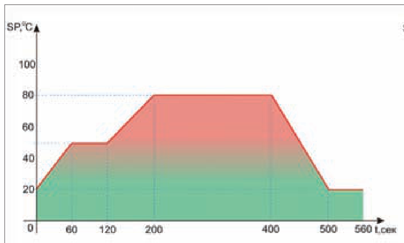
Fig. 2. Piecewise-linear function of time for program No. 1
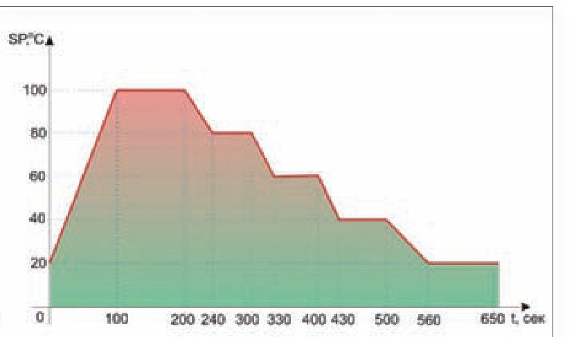
Fig. 3. Piecewise-linear function of time for program No. 2
In total, a MIK-51 program can use up to 9 setpoint generator blocks at once (i.e. up to 9 different programs), each modeling a piecewise-linear function of time with up to 48 segments. This is more than enough for the vast majority of processes.
It is often necessary to correct a PID controller's operation in real time. One example is a furnace draft control loop that takes into account the gas–air ratio (or the gas pressure in the header). Let us take a DKVR-10 steam boiler and, from its operating chart, plot the relationship between furnace draft and gas header pressure (Fig. 4). A sample MIK-51 program that controls this loop automatically is shown in Fig. 5.
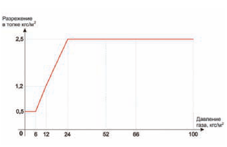
Fig. 4. Relationship between boiler furnace draft and gas header pressure
The program uses a pulse PID controller, since in most boiler houses the gas supply valves are driven by pulse-controlled actuators (MEO).
On the whole, the program contains nothing new, except that two function blocks have been added to the PID loop: analog input block No. 2 (AIN(05)) and the LINEAR(52) piecewise-linear function block. These two blocks implement the curve of furnace draft versus gas header pressure.
Note that the LINEAR(52) output goes to the linked parameter SP_EXT ("external setpoint") rather than to the SP input of the pulse PID block. As a result, the program can work with two setpoints (external and internal). To use the internal setpoint, the controller is switched to local mode ("LU") from the MIK-51 front panel. In that case the furnace draft setpoint entered on the front panel is used, and no correction for gas header pressure is applied. To enable the correction, the controller must be switched to cascade mode ("KU") from the MIK-51 front panel.
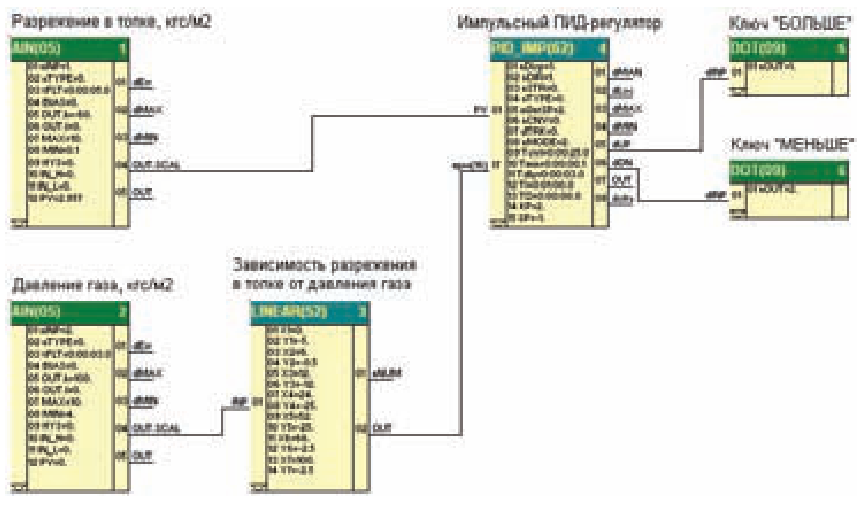
Fig. 5. "Corrected PID controller" program template
This loop is successfully operating on a DKVR-10-13 boiler at Barva CJSC (Yamnytsia village, Ivano-Frankivsk region).
Parallel control loops are needed where the controlled variable must be held at the setpoint with high accuracy. A typical example is a system with one measured variable and two control valves: one on the main line and one on the bypass. A sample MIK-51 FBD program for such a loop is shown in Fig. 6.
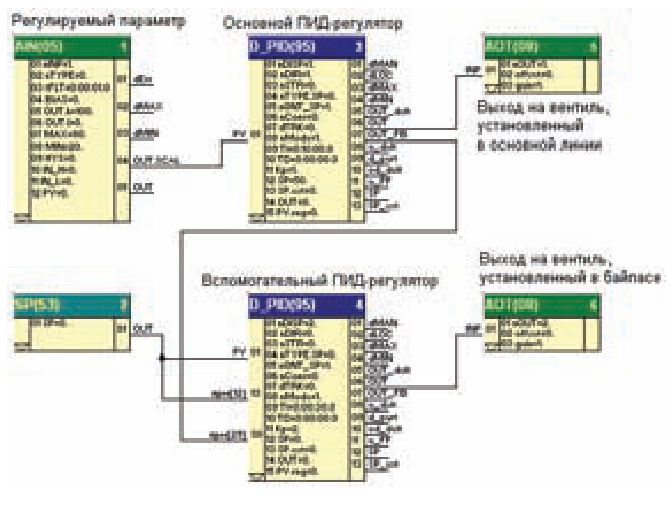
Fig. 6. "Parallel PID controller" program template
The program includes an analog input block, two D_PID(95) delta controller blocks, an SP(53) setpoint block and two AOT(08) analog output blocks. The main PID controller output drives the valve on the main line, and the auxiliary controller output drives the bypass valve.
The highlight of the program is the way the auxiliary PID controller is connected. Its PV (controlled variable) and SP (setpoint) inputs are fed 0 from the setpoint block. The block's input is the linked parameter COR.V (correction value), which receives the signal from the feedback output (OUT_FB) of the main PID controller. Since the main-line and bypass valves usually act in opposite directions, the auxiliary controller parameters are chosen to invert the feedback signal from the main controller. Simply put, the auxiliary controller's correction unit should be set as follows: COR.H = 100, COR.L = 0, COR.G = −1.
Fig. 7 shows a MIK-51 program that controls the device's digital outputs as a "running light". The digital outputs are switched on one after another at 1 s intervals, and once the setpoint (for example, the maximum number of MIK-51 outputs) is reached, they are switched off in the same order, starting with the first one switched on.
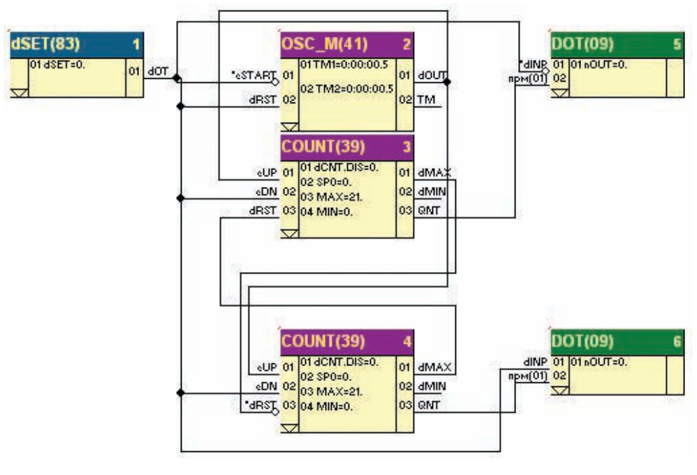
Fig. 7. "Running light" program template
The program consists of 6 blocks: dSET(83) — digital setpoint, OSC_M(41) — multivibrator, two COUNT(39) counters and two DOT(09) digital output blocks. The multivibrator generates a pulse train with a 1 s period (pulse and pause are equal, 0.5 s each). The QNT output of COUNT(39) No. 3 holds the number of pulses counted from the multivibrator, which is in effect the number of the digital output to receive a logical "1". The QNT output of counter No. 4, conversely, holds the number of the output to receive a logical "0". Counter No. 3 runs first (generating the numbers of outputs to switch on); once the MAX = 21 setpoint is reached, counter No. 4 starts (numbers of outputs to switch off).
Readers will probably notice that the program uses only two DOT(09) blocks instead of 21 (one block per output), yet it fully performs the algorithm. The explanation is simple if you look closely at how the DOT(09) blocks are connected. By default, a digital output block has only one input, dINP, and one setting, nOUT. The input tells it what to output ("1" or "0"), and the setting tells it where (which digital output).
The flexible internal program architecture of the MIK-51 allows the nOUT setting to be exposed as a block input ("linking" the parameter). Also note that the value written to a digital output is latched. That is, if you write a logical "1" to, say, digital output No. 5 and then switch to output No. 6 (also writing "1" to it), output No. 5 stays on until a logical "0" is written to it in the same way. This is exactly the approach used in the template. Although it may seem complicated, this technique sometimes offers a way out of apparently hopeless situations.
This template is the heart of the control program for the gas air cooler unit at compressor station CS-39 of the Urengoy–Pomary–Uzhhorod pipeline, where the MIK-51 replaced an obsolete Logistat controller. The program switches the fans on and off in turn (distributing the load evenly) depending on gas temperature. It is possible to specify the fan with which the start-up cycle begins, and to set maximum (to start the switch-on cycle) and minimum (for the switch-off cycle) gas temperature setpoints. The program also includes function blocks that display process variables on the MIK-51 front panel and blocks used in warning and emergency alarm loops.
This way of using digital output blocks made the program much smaller, and the freed-up MIK-51 resources were used for additional alarms, protections and interlocks. The number of fans one MIK-51 can control is limited not by the maximum program size but by the number of digital outputs (21 with the MR-51-15 expansion module).
In conclusion, the examples above are only templates — possible solutions to typical process control tasks. We hope that readers who work through this article will be able to use it as a basis for programs that fully meet their requirements.
For more information about the products mentioned in this article, please contact Microl LLC:
+38 (0342) 502-701
+38 (067) 359-70-90
+38 (095) 092-07-28
sale@microl.ua, microl_zbut@microl.ua, zbutmicrol@gmail.com
www.microl.ua
Technical support:
+38 (0342) 502-702
+38 (067) 704-00-29
+38 (095) 302-37-57
support@microl.ua, supmicrol@gmail.com
Originally published in Mir Avtomatizatsii (World of Automation) magazine, No. 5, October 2009.
Open the booklet / download PDF