











Archive
18.11.2026


 0
 0
 Touch operator panels Weintek
 Meters-indicators
 Controllers (PID, ON/OFF)
 I/O modules

I/O modules
 Spark protection barrier

Spark protection barrier
 Recorders and archivers

Recorders and archivers
 Meters and converters of electrical network parameters

Meters and converters of electrical network parameters
 Counters, timers, tachometers

Counters, timers, tachometers
 Liquid level indicators and regulators

Liquid level indicators and regulators
 Programmed logical controllers

Programmed logical controllers
 Manual signal transmitters

Manual signal transmitters
 Technological signaling devices

Technological signaling devices
 Power supplies

Power supplies
Codesys PLC controllers
Codesys PLC controllers
 Normalizing converters

Normalizing converters
Galvanic isolation and branching blocks
Galvanic isolation and branching blocks
 Communication interface converters and amplifiers

Communication interface converters and amplifiers
 Analytical instruments

Analytical instruments
 Switching blocks

Switching blocks
Control and protection units
Control and protection units
 GSM communication routers / modems

GSM communication routers / modems
Archive
18.11.2026
Author
Valerii Dykhnilkin, Volodymyr Kapustiak, Microl LLC
E-mail: asutp@microl.ua
The equipment of most heat substations in our country is outdated and cannot cope with today's tasks. Replacing all the process equipment is usually expensive, so the most sensible option is to upgrade substations with modern microprocessor control systems.
Historically, the development of the former, now non-existent country rested on three pillars: consolidation, expansion and growth. We were always increasing something, chasing the West in the amount of "something" per capita, building the biggest ships and aircraft, excelling in the arms race… We had "the very best" of everything: the happiest childhood, the most prosperous life and the brightest future ahead. Resources were considered, if not infinite, then at least sufficient for a long time. Nobody took saving seriously.
But nothing lasts forever. The consolidation of production, the expansion of capacity and the growing demand for raw materials became one of the reasons for the difficult state of Ukraine's economy. And the current crisis has once again shown how unstable our country's industries are.
The crisis has also affected the country's energy sector, including district heating. We inherited large boiler houses and an extensive network with many heat substations, with outdated process equipment and rather worn-out instrumentation. Nothing substantial can be done with the process side (in terms of upgrading) for the simple reason that there is no money. But the instrumentation can and should be replaced. The reliability of the control loop and the efficiency of the whole installation depend directly on how well the control devices work, and this in turn determines how much fuel and energy is saved.
Given the likely budget for upgrading process control systems, using foreign instruments would be somewhat problematic. The fair question then is: what should be used? Preferably domestic products, with a minimum of trouble during design, installation and commissioning. Do such instruments exist?
It turns out they do, and there is more than one solution. One option is the Ukrainian-made multifunctional controllers produced by Microl (Ivano-Frankivsk).
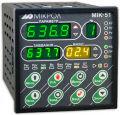
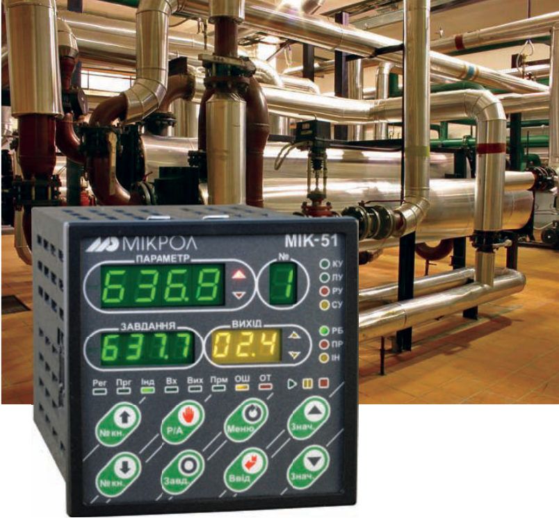
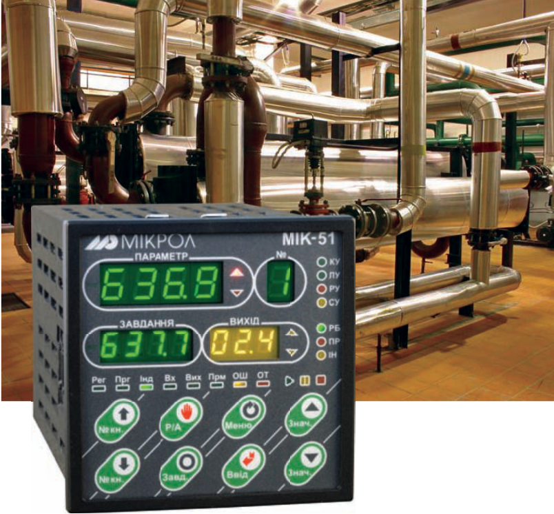
The MIK-51 controller series has already been covered in Mir Avtomatizatsii. This article describes a complete automation system based on MIK-51 controllers. As the object, we take a central heat substation (CHS) — the intermediate link between the heat source and the consumer in a district heating system.
The task is as follows. A typical central heat substation supplies hot water to a small city neighborhood. For simplicity, we consider only the part of the process responsible for hot water supply and leave out the heating water loop. A simplified process diagram of the substation is shown in Fig. 1. All substation loops must be controlled automatically, the automation system must be monitored remotely from the central emergency dispatch center, and the substation must be controllable remotely if necessary.
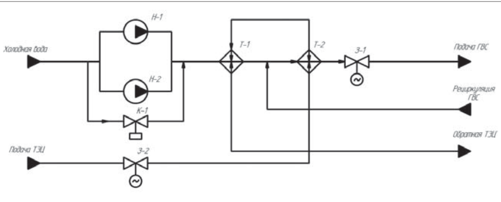
Fig. 1. Simplified process diagram of the heat substation
Now briefly about the process. Cold mains water is fed to the first-stage heat exchanger (T-1) by pumps N-1 and N-2 or through a bypass. In T-1 the water is heated and goes to T-2 (the second-stage heat exchanger), at whose outlet it reaches the required temperature. The water is then supplied to consumers. Part of the water returns to T-2 via a recirculation line. The heat carrier from the CHP plant passes through the hot water control valve, first to T-2 and then to T-1 (where it heats the water), and returns to the CHP plant via the return line.
Fig. 2 shows the block diagram of the central heat substation control system. It was designed to keep capital investment in the substation's process equipment to a minimum. The system does not require replacing old pressure, temperature and flow sensors or installing new actuators, dampers and pumps. It uses the equipment already installed, supplemented with a few instruments and, if additional control loops are needed, new sensors and actuators. The heart of the system is a pair of MIK-51 controllers that perform all substation control functions. A variable frequency drive is provided for pumps N-1 and N-2. Since the pump motors are usually no larger than 5–6 kW, a Danfoss FC-51, for example, can be used. The drive output goes to a "Duty"/"Standby" switching circuit controlled by the MIK-51, and from there to the motor of one of the pumps.
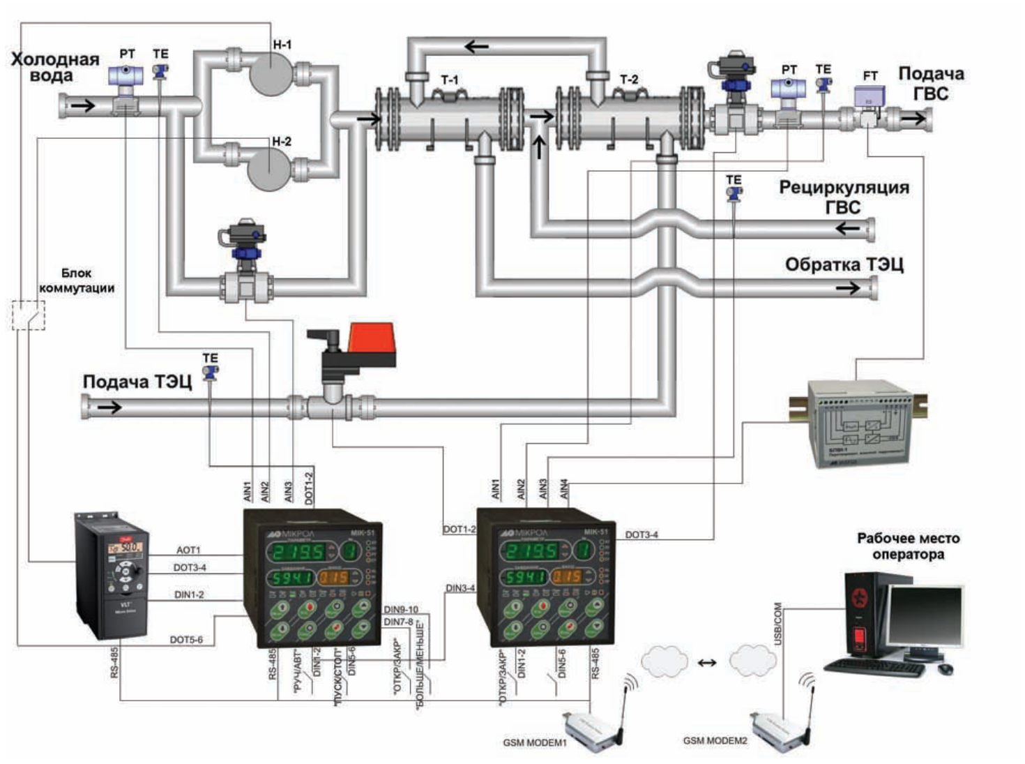
Fig. 2. Block diagram of the central heat substation control system
The frequency drive and both controllers are connected in a peer-to-peer RS-485 network (Modbus RTU protocol). The controllers communicate with the computer at the central emergency dispatch center wirelessly via GSM modems. This approach is preferable in urban conditions, as it allows an extensive network linking all substations to the dispatch center to be set up at minimal cost.
Depending on needs, manual and automatic control loops and units generating various digital signals for information, pre-alarm and alarm functions can be added to the system.
The supervisory computer communicates with the system cabinet through the Visual Intellect SCADA system (Fig. 3). This SCADA system, developed by Microl, is a universal tool for building an operator workstation. Together with modern MIK-51 microcontrollers, Visual Intellect makes it easy to monitor the whole system remotely, control all its loops and produce a variety of reports per shift, day, month, year and so on.
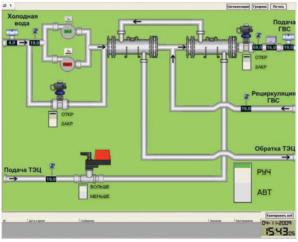
Fig. 3. Visual Intellect SCADA system window
Capabilities of the central heat substation control system:
If necessary, the following can be added:
As you can see, reworking the automation of a central heat substation, although minor in terms of hardware, brings fundamental qualitative changes in control, significant resource savings thanks to smarter and more rational operation of the substation loops, and the ability to monitor it remotely. All this comes at minimal cost and is based on domestic equipment (apart from the frequency drive, although there are options here too — for example, products from the Triol corporation). Moreover, the system is not rigidly fixed, and its functionality can be expanded further if needed.
For more information about the products mentioned in this article, please contact Microl LLC:
+38 (0342) 502-701
+38 (067) 359-70-90
+38 (095) 092-07-28
sale@microl.ua, microl_zbut@microl.ua, zbutmicrol@gmail.com
www.microl.ua
Technical support:
+38 (0342) 502-702
+38 (067) 704-00-29
+38 (095) 302-37-57
support@microl.ua, supmicrol@gmail.com
Originally published in Mir Avtomatizatsii (World of Automation) magazine, No. 6, December 2009.
Open the booklet / download PDF