













Archive
18.11.2026


 0
 0
 Touch operator panels Weintek
 Meters-indicators
 Controllers (PID, ON/OFF)
 I/O modules

I/O modules
 Spark protection barrier

Spark protection barrier
 Recorders and archivers

Recorders and archivers
 Meters and converters of electrical network parameters

Meters and converters of electrical network parameters
 Counters, timers, tachometers

Counters, timers, tachometers
 Liquid level indicators and regulators

Liquid level indicators and regulators
 Programmed logical controllers

Programmed logical controllers
 Manual signal transmitters

Manual signal transmitters
 Technological signaling devices

Technological signaling devices
 Power supplies

Power supplies
Codesys PLC controllers
Codesys PLC controllers
 Normalizing converters

Normalizing converters
Galvanic isolation and branching blocks
Galvanic isolation and branching blocks
 Communication interface converters and amplifiers

Communication interface converters and amplifiers
 Analytical instruments

Analytical instruments
 Switching blocks

Switching blocks
Control and protection units
Control and protection units
 GSM communication routers / modems

GSM communication routers / modems
Archive
18.11.2026
Author
Based on materials from ADVES LLC: S. V. Krainii, head of the process control department; M. I. Katerenchuk, electric drive engineer
Variable frequency drives combined with a controller can noticeably reduce the electricity consumed by boiler drives and save gas. Below is a brief overview of a project to upgrade DKVR and DE boilers, in which the gas–air ratio is controlled by a MIK-51 controller made by Microl LLC.
In 2007, seven DKVR and DE boilers were automated at the Brovary heating network under a program of Ukraine's Ministry of Housing and Utilities. The work was carried out by ADVES, the official distributor of Emotron AB. Instead of replacing the boilers with new imported ones, the existing boilers were upgraded: their efficiency was raised to 90–92.5 %, and no design work was needed because the boilers' process equipment was not changed. The old control system was kept as a backup and integrated into the new one, so it can be made the main system again at any time.
The new boiler control system provides:
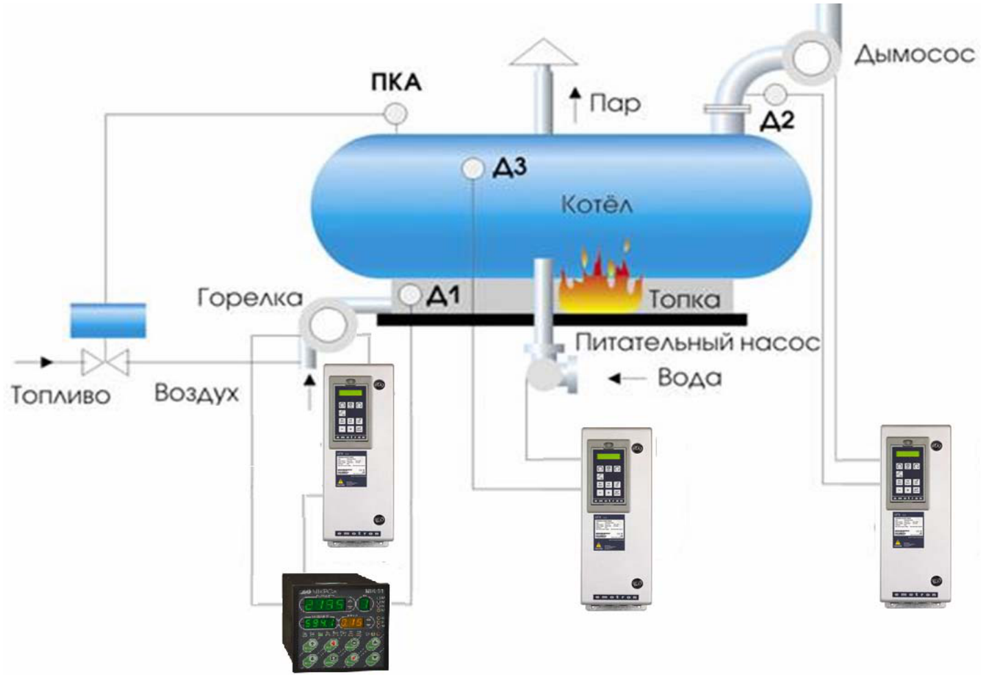
Fig. 1. Block diagram of the boiler control system
The fans and the induced-draft fan are driven by Emotron FDU series frequency converters designed specifically for fan and pump applications. They run reliably on supply networks with poor power quality and use scalar control, which is fully sufficient for this application.
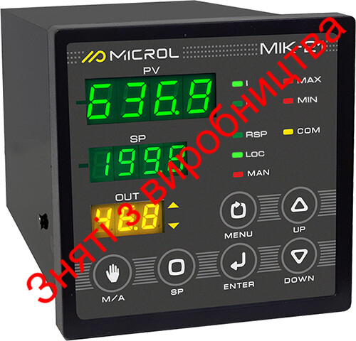
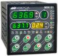
The gas–air ratio is controlled by a MIK-51 controller (Fig. 2). The project authors note the reliability of Microl products, the controller's compliance with the technical requirements, its good value for money, and the easy-to-use software for writing the control program. Air and gas pressure transmitters are connected to two of the MIK-51's four analog inputs; the other two are kept in reserve — for example, for a flue gas oxygen sensor and ratio correction. The controller's PID loop was tuned individually for each boiler, which considerably shortened transients. The MIK-51 output goes to the frequency converter, which changes the motor speed.
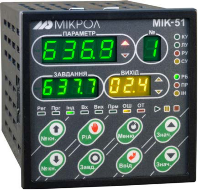
Fig. 2. MIK-51 multifunctional controller
The boiler control program was developed jointly by ADVES and Microl engineers, the boiler manufacturer and service heat engineers. Operators now see exact gas and air pressure values on the controller's digital displays instead of draft gauges. For light-off, when a small air flow is needed, the MIK-51 program provides manual setpoint entry from the front panel, so the flame does not blow out. An automatic linear operating chart was drawn up for the boilers; oxygen and CO2 sensors installed at the customer's request confirmed that the boilers operate at the optimal point.
Draft at the induced-draft fan is controlled by a PID controller built into the frequency converter itself, using the signal from the draft sensor; the speed ramp of the high-inertia drive was tuned accordingly.
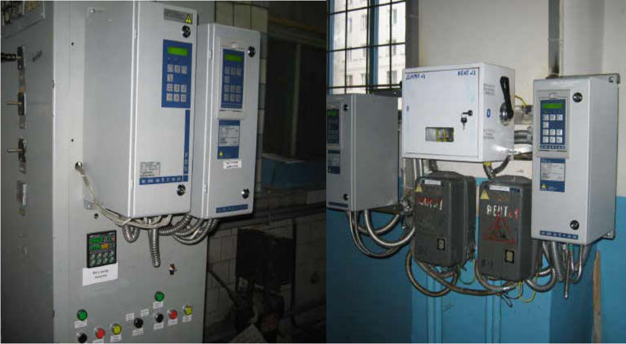
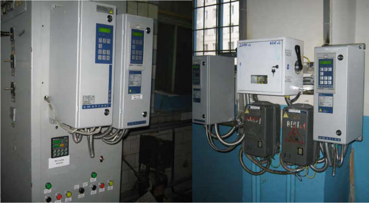
Fig. 3. Boiler control system
This control scheme is also being introduced at other enterprises.
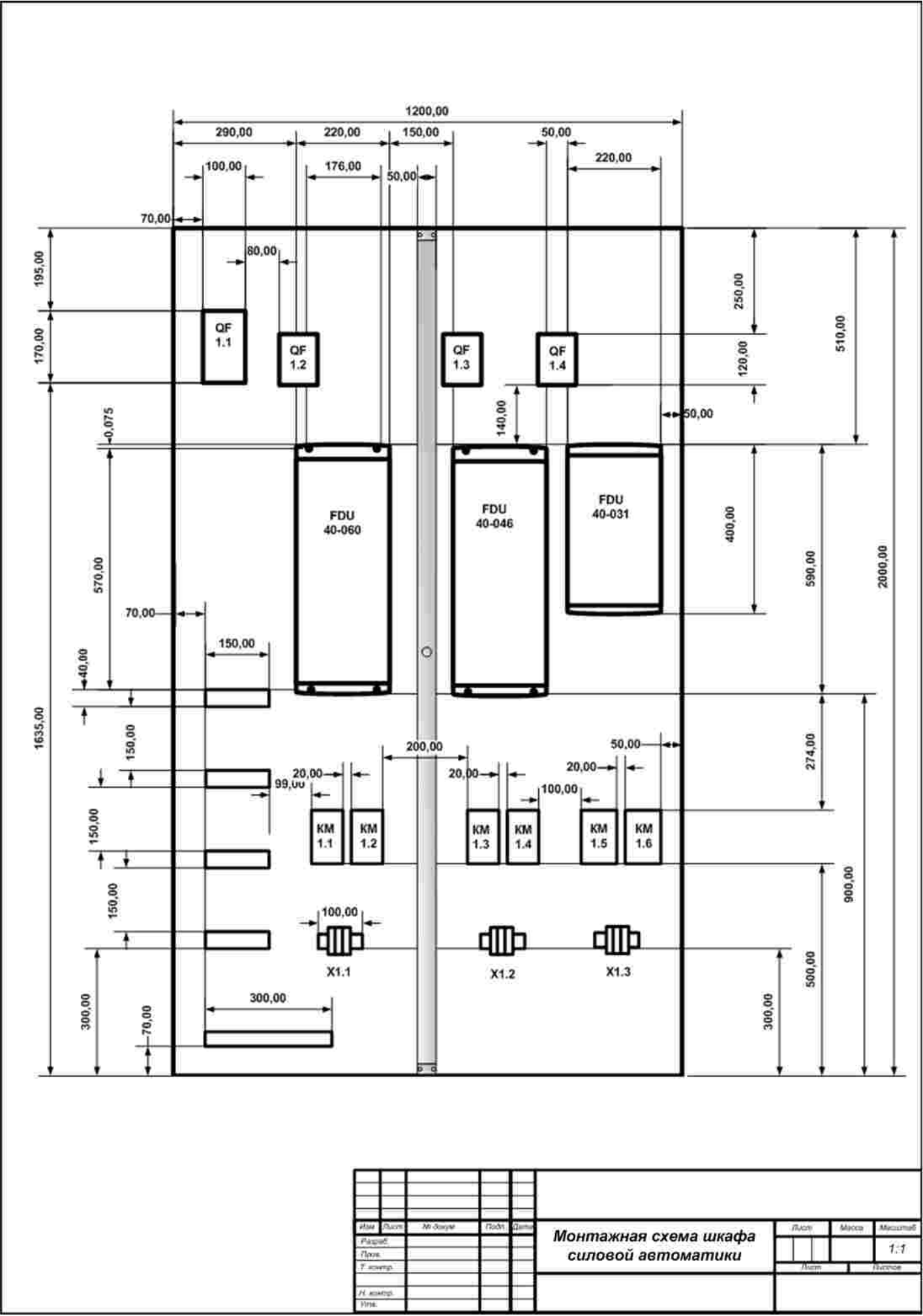
Assembly drawing of the power automation cabinet
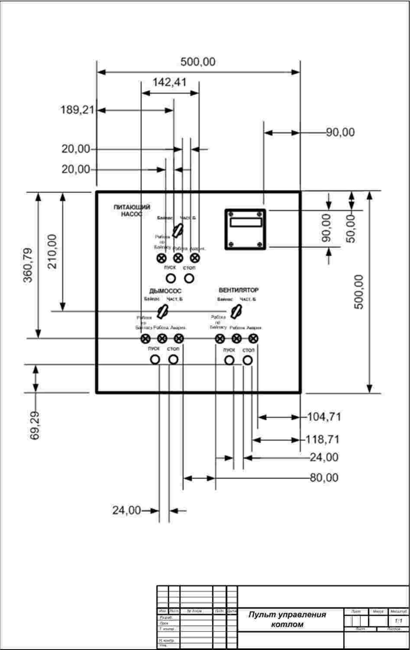
Boiler control panel
For more information about the products mentioned in this article, please contact Microl LLC:
+38 (0342) 502-701
+38 (067) 359-70-90
+38 (095) 092-07-28
sale@microl.ua, microl_zbut@microl.ua, zbutmicrol@gmail.com
www.microl.ua
Technical support:
+38 (0342) 502-702
+38 (067) 704-00-29
+38 (095) 302-37-57
support@microl.ua, supmicrol@gmail.com
Prepared on the basis of materials from ADVES LLC (www.adves.biz) on the boiler upgrade at the Brovary heating network.
Open the booklet / download PDF